One of the best parts about coding for the Commodore Amiga is having access to the wonders of the Copper. This tiny co-processor is part of the Amiga custom chipset and it's responsible for many of the more impressive graphical effects you see in games or demos. While many effects are possible with the Copper, one of the more common ones is its ability to change the value of colour palette entries while the screen is being drawn. This is often used to draw a gradient in the background of games, but the Copper can change way more than just one colour per line.
With that in mind, I decided to try my hand at turning the Copper colour change effect up to 11.
Copper Chunky
With that in mind, I decided to try my hand at turning the Copper colour change effect up to 11.
Copper Chunky
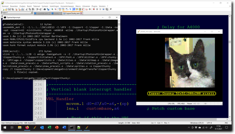
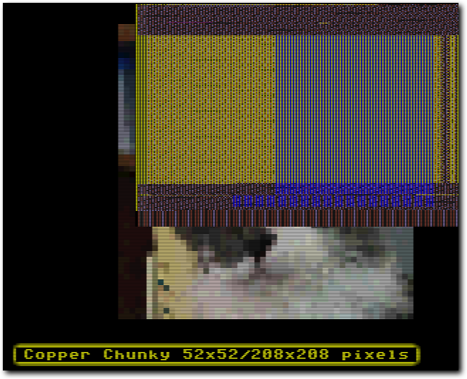
Above: testing the Copper Chunky program in WinUAE.
I ended up implementing a Copper Screen / Copper Chunky mode designed with the limits of the Amiga 500 in mind. This is a screen mode in which all the pixels you see are only created by the Copper - the normal bitplane display is only used to create the pixel grid the Copper 'draws' to.
Such a screen mode allows for a theoretical maximum of 57 colours per line (though in reality you'll not reach this due to required overhead). But, there is a catch. The Copper can change only change one colour for every 8 pixels in the best case. This would mean one 'pixel' would be at least 8 pixels wide, which is usually too big to be useful. However, there is a solution: if the Copper reloads most of the colour registers ahead of where they are used and the bitmap used has a specific pattern, it's possible to create a screen that appears to have one colour change every four pixels. The only drawback using this method is that it means can't be as wide as the screen itself.
Now, setting up a Copperlist and background like this still poses some problems. The first is that a wide screen will need more than 16 colours and the Copper slows down if more than 16 colours are being shown (colour changes take 12 pixels when using 32 colours and 16 pixels when using EHB/Dual Playfield). The second is that PAL Amiga's give 113 slots for the Copper, which is not readily divisible by two (which is the amount of cycles a Copper MOVE and Copper SKIP take).
Solving the first problem relies on using a very interesting quirk of the OCS chipset. If you set the number of bitplanes to 7, rather than the normal maximum of 6 something strange happens. The display will work as if it has 6 active bitplanes, but Agnus will only fetch 4 of them. This means that the 5th and 6th bitplane will normally be empty and the screen will show 16 colours. Not only that, but it will also only use the DMA cost for a 16 colour screen, so the Copper runs at full speed. How does this help us?
Well, the quirk allows you to set the BPL5DAT and BPL6DAT registers to a pattern of your choice. This means we can have a 16 pixel wide repeating pattern of data for bitplanes 5 & 6. With that we can make it so that some pixels on the screen will display colours 16-31 (or EHB equivalents) while the rest displays colours 0-15. Couple this with a strategically chosen background pattern and it's possible to display all 32 colour registers while using no more DMA time/memory than is used by a standard 16 colour screen.
However, there is a rather big issue with the above quirk: it does not work on AGA machines. This means that the Copper Chunky effect in this example relies on mixing 64 pixel wide hardware sprites with a 16 colour screen instead on AGA systems. The upshot is that the effect now works on AGA, but it should be noted that in its current form it's not AGA optimised, merely equal to the OCS/ECS version.
Solving the second problem requires very precise Copper timing (which is display standard specific, this version only works on PAL machines) to be used, which effectively allows a Copperlist to 'skip' the 113th cycle, so that division by 2 becomes possible. With these two problems fixed, I was able to create a Copper Screen/Copper Chunky mode that was 208 pixels wide (=52 'Copper Pixels'). I decided to keep the resulting image square, so the final resolution of my Copper Screen is 208x208 pixels.
- Method
- Chunky Screen
- Effects
- Scripts
- Performance
- Notes
Tab 1
The Copper Chunky example is made up of three distinct elements: the Copper Chunky screen, the Amiga side effects code and the PC side effect scripts. Each of these play a different role in the final example.
The Copper Chunky screen code generates and updates the Copperlists which are used to show the 52x52 chunky pixels screen mode. The Amiga side effects code updates the pixel data as shown on the screen. The PC side effect scripts are used to pre-calculate pixel offsets and delta's into the source images.
The Copper Chunky screen itself is aligned to the right of the screen. This is done to make it easier to read the Copperlist and to make the conversion between chunky pixel coordinate and offset into the Copperlist less complicated. Note then that it's definitely possible to have the effect anywhere on the screen, the choice here was purely for legibility.
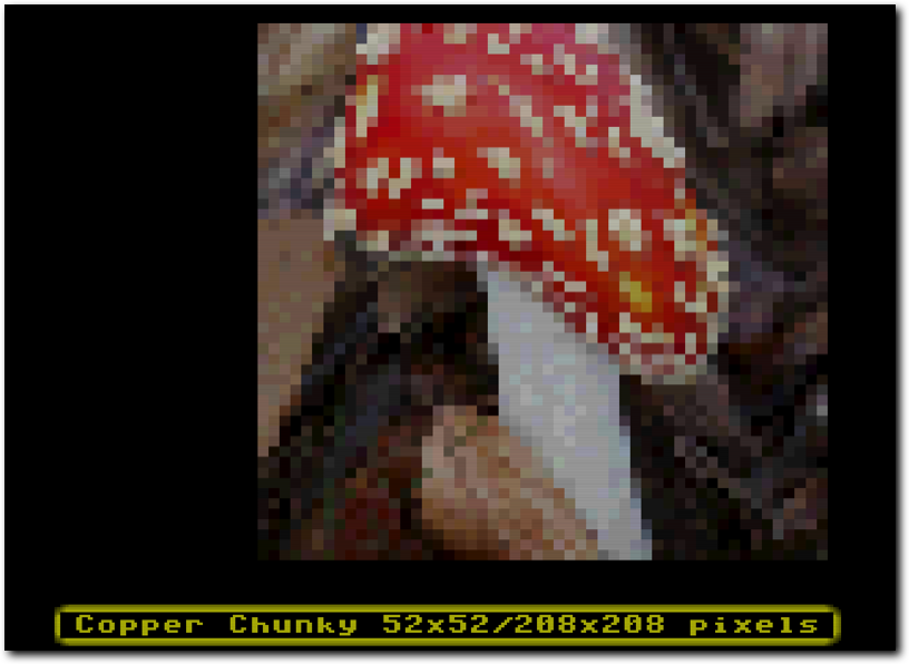
Above: the final result, a Copper Chunky screen capable of showing various effects.
Currently, there are currently three supported effects. The first effect is a skew effect, in which pixels are skewed either horizontally or vertically (currently only skewing through the X-axis is supported in the example). The second effect is a zoom effect, in which the source image can be zoomed in or out of dynamically. The third and last effect is a rotation effect, which rotates the source image, optionally adding a zoom.
While the Amiga side effects code is very similar for each, the effects have still been implemented in separate routines. The idea here is to make it easier to understand how each of these effects works by having the small differences between each isolated from the rest of the effects.
While the Amiga side effects code is very similar for each, the effects have still been implemented in separate routines. The idea here is to make it easier to understand how each of these effects works by having the small differences between each isolated from the rest of the effects.
Tab 2
All Copper chunky screen modes essentially work in the same way. They all use the Copper to rapidly reset one or more colour registers, to change the colours shown on screen. In a way, the Copper chunky screen is a much more extreme form of the Copper rainbow effect (also known as a Copper gradient) as seen in many games. Where the various Copper chunky screen modes differ from each other is in how they approach the problem and what tricks (if any) they use to get more chunky pixels onto screen.
The basic problem is this: in the best case scenario, the Copper can change one colour every 8 on screen lowres pixels*, but this leads to a very low resolution on the screen if used to create pixels (around 40 chunky pixels will fill one screen line). This low resolution, while certainly interesting for some effects, does not create very appealing images. It's also not very efficient: the Copper can do around 56-57 of these register changes per line, but this effect would only use 40 of them for colours, leaving the rest unused.
What would be much better is if those extra potential register changes could also be used to create extra chunky pixels. And this is indeed possible: by using extra colour registers and a special pattern on the screen, those extra 16 register changes can be used to add more chunky pixels to the screen. The result of doing this would lead to 56 colours per line, or one new chunky pixel every 5,7 pixels. However, this would still not be very optimal. The OCS/ECS Amigas have 32 colour registers, but this effect only manages to use 17 of them. It would be better still if some arrangement of register writes/screen pattern can be found that allows for more registers to be used.
To achieve this, Copper chunky modes exchange the horizontal size of the effect for more colour registers being used in the effect. The consequence of this is that the individual coloured pixels will shrink in size, which leads to a smaller, higher resolution image (though the maximum number of colours that can be changed per line does not change). The way this is done is by changing more colour registers ahead of the chunky pixels being shown, while reducing the amount of colours being changed during the chunky pixels being shown. Because of the Copper maximum of one register change every 8 pixel, the optimal chunky pixel size ends up being one chunky pixel every 4 low res pixels.
One of the core advantages of a chunky screen over a bitplane based screen is that you can change the colour of a pixel with a single write in memory, rather than needing as many as there are bitplanes. For some type of effects, in particular raycasting, zooming and rotation, this is very useful. However, the method as described above will require one write for every line the colour needs to be changed on. This means that a 4x4 chunky pixel would require 4 writes into memory to be updated.
To fix this, Copper chunky modes usually make use of a loops in the Copperlist, which repeat the exact same instructions several times. When this method is used, only one write will be needed to update all lines of a pixel at once. This increases performance significantly, at a small cost in Copperlist overhead. This overhead drops the number of registers that can be changed from 56-57 per line to 52 per line - the remaining time is needed for the Copper loop.
One last problem needs to be fixed for the Copper chunky screen to be work as desired and that is the speed at which the Copper can change registers. As pointed out, the Copper can change one register every 8 low res pixels in the best case scenario. However, this best case scenario requires the use of a screen mode with 4 or fewer bitplanes (<=16 colours). The effect described above will require more than 16 colour register, which would mean the Copper would be slower.
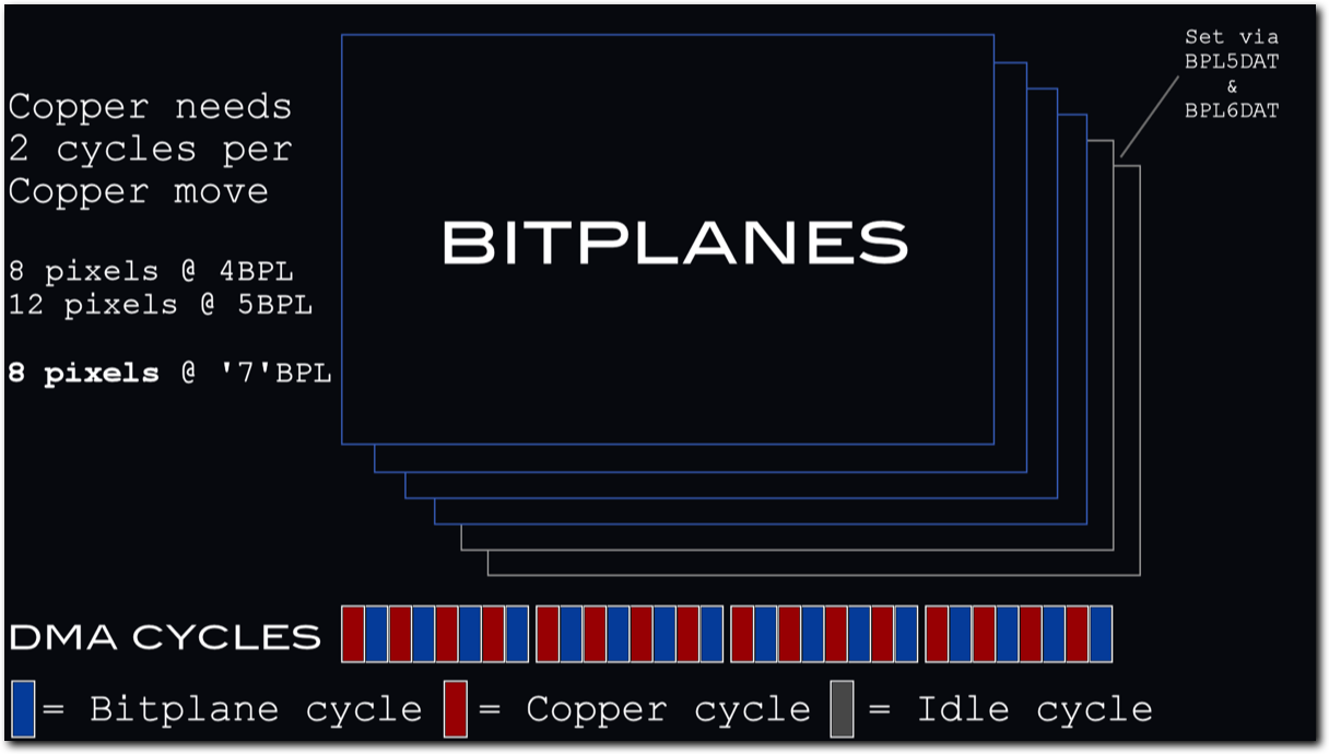
Above: "Seven bitplane mode" uses DMA memory access as if four bitplanes have been selected, while displaying all six.
Luckily, there is a way around this, by using an undocumented hardware feature of the OCS/ECS custom chip set. The maximum number of bitplanes on these systems is 6, setting the number of bitplanes to 7 confuses the system. This confusion results in a screen that shows all 6 bitplanes, but only fetches 4 from memory. This means the Copper will run at its full 8 pixels per register change. In this mode, bitplanes 5 and 6 will default to showing nothing. They can now be manually set using writes to BPLDAT5 and BPLDAT6. These writes allow for a 16 pixel wide pattern to be shown on bitplanes 5 and 6.
The example program I made uses this trick to display a special pattern onto the screen which allows the use of more than 16 colour registers.
The example program I made uses this trick to display a special pattern onto the screen which allows the use of more than 16 colour registers.
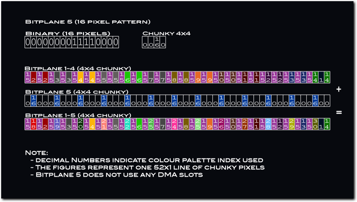
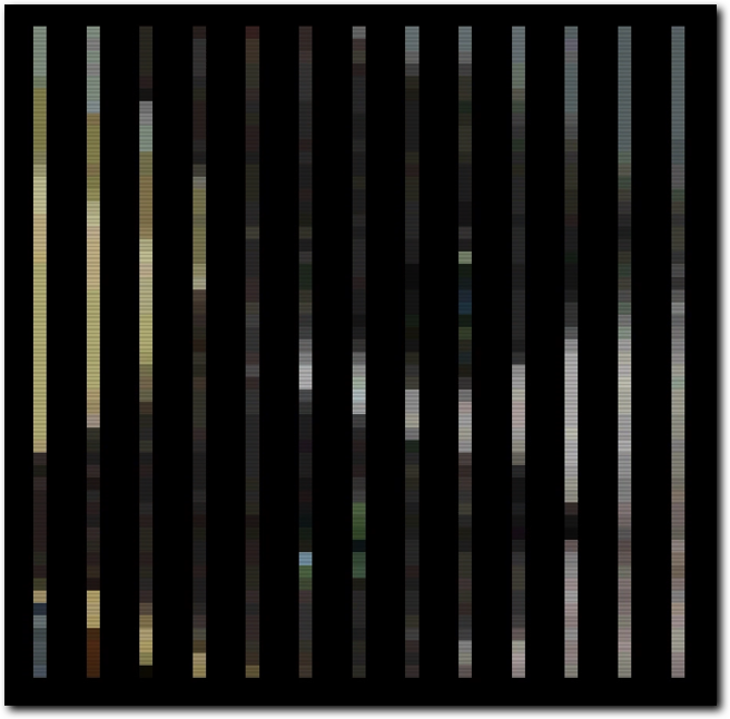
Above: a special colour pattern is used (repeating every line) to make a four pixel wide chunky pixel resolution possible
At this point, it needs to be mentioned that this trick does not work on AGA systems and has to be emulated. Luckily, the AGA chipset offers 64 pixel wide sprites. By strategically covering pixels using Sprites, the same effect can be achieved while only using a 4 bitplane screen. The example program will automatically switch to using this hardware Sprite method if AGA is detected.
The end result is a 52x52 chunky pixel screen, which covers 208x208 pixels.
*) Changing resolution doesn't increase the Copper's speed, it always takes at least 8 lowres pixels to change a register. As such, changing to hires or superhires will not increase the number of colours/chunky pixels that can be shown using this method.
Tab 3
The example currently supports three effects: zooming, rotating/zooming and skewing. All three run at 50FPS and all three use several tricks to maintain this performance. The reason for requiring tricks is that even simplified versions of algorithms for zooming and rotating are quite hard to do in real time on a 7MHz 68000.
In order to maintain full frame rate, all effects make use of pre-calculated X & Y delta/offset tables. These tables are used to determine how many (if any) pixels to skip in the source image per destination pixel. Using such tables, all three effects can be achieved. These tables are generated by the supplied Python scripts (see the Scripts tab for more information on how they are generated and which algorithms are being used).
The rest of the basic setup for the effects is as follows:
- Raw 12 bit images (one word per pixel containing the colour value) are used as the source images.
- In all cases, the source images are quite a bit larger than the final 52x52 image that is displayed. For reference, the size for the source images is currently set to be 208x208 pixels.
- Like the destination image, all source images are also square shaped. Note that this is not technically required for the effect to work, but all scripts supplied with the example assume this to be the case.
- The effects use additions only during the inner loops that generate the output frames.
- Inner loop code is fully unrolled for maximum performance on 68000.
- Effects code writes directly into the Copperlist without intermediate steps for performance.
- A double buffered Copper list is used: one Copper list is displayed while the next is created.
- All effects code assumes a maximum x & Y delta/offset er pixel that fits inside a 16 bit value.
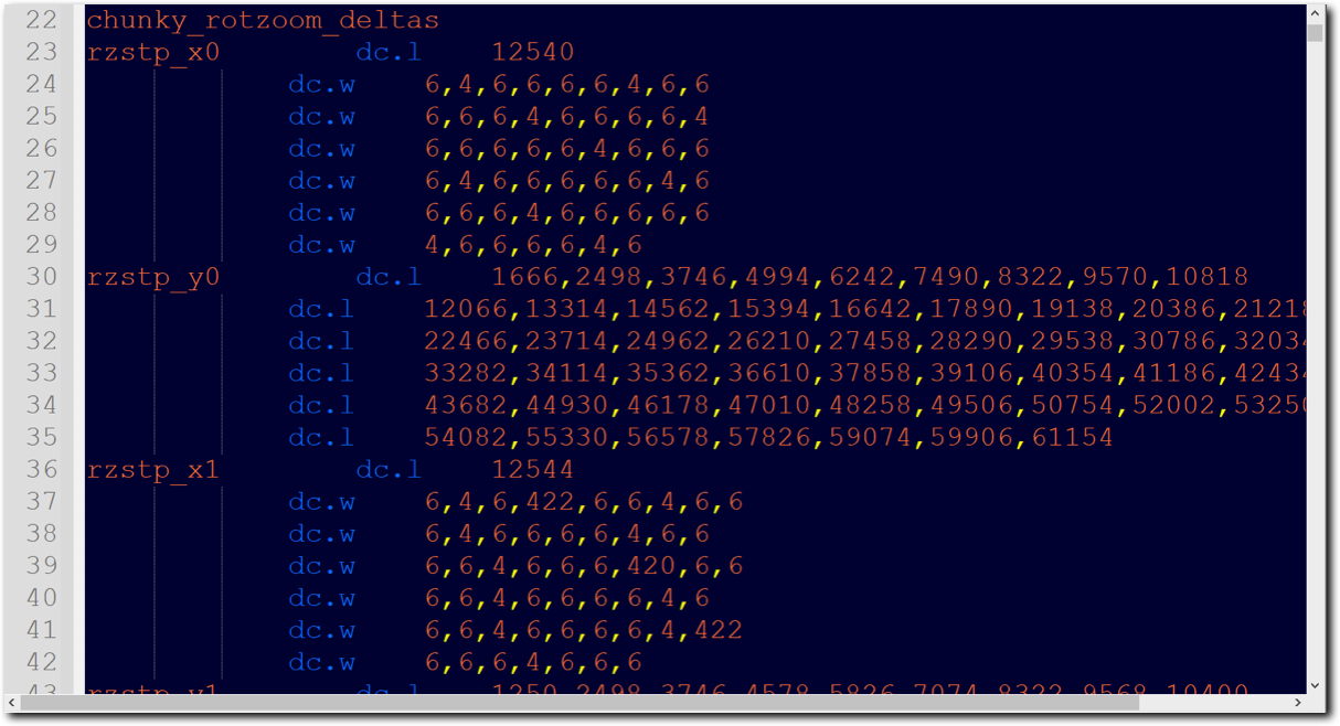
Above: part of one of the pre-calculated tables responsible for the effects.
Other than the choice of delta/offset tables, the main differences between the various effects are the parameters that are passed to the routines and the exact operations done per pixel. The three effects differ as follows:
Skew
Zoom
Rotate/zoom
Skew
- Parameters: static x,y offset into source image, dynamic x delta table, static y delta table
- Setup: apply starting x,y offset into source image (unchanging value)
- Inner loop: add delta to x coordinate, then fetch source pixel(x,y)
- Outer loop: add offset to y coordinate
Zoom
- Parameters (option 1): dynamic offset into source image (same offset for x & y), dynamic delta table (same table for x & y)
- Parameters (option 2): dynamic offset into source image (same offset for x & y), dynamic delta tables for x & y
- Parameters (option 3): dynamic x & y offset into source image (different offsets), dynamic delta tables for x & y
- Setup: apply starting x,y offset into source image (changes per frame)
- Inner loop: fetch source pixel(x,y), then add delta to x coordinate
- Outer loop: add delta to y coordinate
Rotate/zoom
- Parameters: dynamic x offset/delta table, dynamic y offset table
- Setup: apply starting offset value into source image (value in bytes, changes per frame)
- Inner loop: fetch source pixel(x,y), then add delta to x coordinate
- Outer loop: change x,y coordinate to new source coordinate via offset from 0,0
Tab 4
The delta & offset tables used by the effects are created by a number of Python scripts. Each script implements an algorithm to pre-calculate the correct values to use for the delta/offset tables to achieve either skewing, zooming or rotation/rotation with zoom. Two of these algorithms were sources from internet sources and adapted for use in this example, while one was created from scratch. Note that the rotation with zoom and the rotation without zoom both use the same algorithm.
Each of the Python scripts generates an assembly source file which contains a set of pre-calculated tables that are used by the Amiga side of the effects. The Amiga program then uses a separate script to select which parts of the tables to use during which frame. The tables created by the script contain one entry for each x or y coordinate in the destination image. In the case of this example, that means each table contains 52 entries. As the destination image is generated on the Amiga based on the source image, the tables are stepped through as each coordinate is drawn.
Each of the Python scripts generates an assembly source file which contains a set of pre-calculated tables that are used by the Amiga side of the effects. The Amiga program then uses a separate script to select which parts of the tables to use during which frame. The tables created by the script contain one entry for each x or y coordinate in the destination image. In the case of this example, that means each table contains 52 entries. As the destination image is generated on the Amiga based on the source image, the tables are stepped through as each coordinate is drawn.
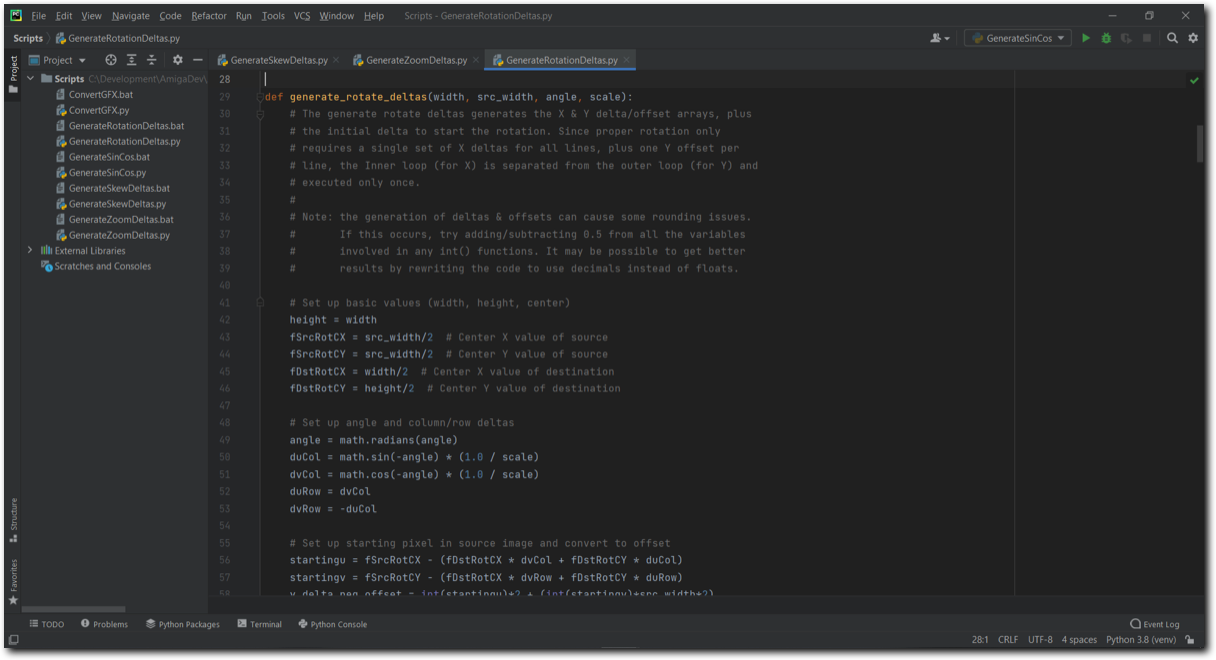
Above: part of one of the Python scripts for calculating the tables.
Zoom
The zoom script makes use of the Bresenham zoom algorithm, which achieves accurate zooming using only integer values by using an integer part and a fractional error part. The original C based source code and explanation for this algorithm were sourced from Dr. Dobbs (https://www.drdobbs.com/image-scaling-with-bresenham/184405045). The zoom script ends up creating many tables: one table for each axis and each individual zoom level that is supported. For each second the zoom effect lasts, 50 tables are needed for both the X and Y direction.
Rotation
The rotation/zoom script makes use of a fast rotation algorithm found on Dr. Dobbs (https://www.drdobbs.com/architecture-and-design/fast-bitmap-rotation-and-scaling/184416337). What's particularly interesting about this method is that it is a C reimplementation of code originally used for creating Amiga demo effects. This algorithm makes use of the fact that rotation can be expressed as a (slight) zoom and shearing/skewing over both the x and y axis. Like the zoom algorithm, the Python code is written such that it outputs only integers. The script generates many tables: one table for each axis and each individual degree of rotation/zoom that is desired. The example program rotates a single degree per frame and has both a rotation without zoom and a rotation with zoom, so the script has to generate 4*360 tables in total.
Skew
The skewing script combines the Bresenham zoom algorithm set to a static zoom level with a chosen per pixel offset for either the X or the Y axis*. The per pixel offset is generated using a simple sine wave (though any algorithm could be used). For each second the skewing effect lasts 50 tables are needed for either the X or the Y direction.
*) Note: the example currently only supports skewing over the X axis.
Tab 5
The example runs fully at 50Hz, meaning all effects run in less than one frame on an A500 (though each effect varies slightly in exact raster time used). On average, about 19 raster lines are still free - or about 6% CPU. The main two performance limiters are the Copper overhead and the CPU cost of updating the pixels.
In the setup used by this example, the Copper executes 54 Copper move instructions and one Copper skip instruction for each of the 208 lines shown. This comes to a total of 22880 DMA cycles, or 32% of all available cycles in a frame. Since the Copper instructions interleave with the 4 bitplane screen, there is no CPU time available during bitplane fetches (which last 224 pixels). Essentially, the chunky display blocks the CPU for 112 cycles every displayed line. In total this slows down the CPU by around 16%.
The slowdown of the CPU means the effects all have to be made very much with speed in mind and are very limited in terms of how many instructions can be executed per pixel.
Above: the WinUAE Visual DMA Debugger shows the large amount of Copper DMA cycles (shown in yellow) on the bus.
However, it should be pointed out that this version of the Copper Chunky effect is primarily meant to showcase how to achieve the effect - not to be the fastest possible implementation. With that in mind, it might be nice to look at a more optimal setup that can also be used. This setup was used by Scoopex in their demo 'Grade My Waterbear' (http://www.pouet.net/prod.php?which=66955) and is probably the fastest method currently available for OCS systems.
The idea is to use Sprites (running with DMA disabled so they repeat a fixed pattern over the height of the screen) to cover as many pixels as possible and only use bitplanes to cover the remaining pixels. Doing this leads to a screen that covers almost as many pixels as the example presented here, but with a much lower DMA overhead. In essence, the Scoopex version of the effect gets back most of cycles the CPU lost in the more traditional version shown here.
The idea is to use Sprites (running with DMA disabled so they repeat a fixed pattern over the height of the screen) to cover as many pixels as possible and only use bitplanes to cover the remaining pixels. Doing this leads to a screen that covers almost as many pixels as the example presented here, but with a much lower DMA overhead. In essence, the Scoopex version of the effect gets back most of cycles the CPU lost in the more traditional version shown here.
Tab 6
AGA
As pointed out elsewhere in the article, the trick used to achieve the Copper chunky mode doesn't work for AGA systems. In the example program, this problem is fixed by using AGA hardware sprites to cover the pixels that could not be used. It should be pointed out that this method, while it certainly works, is not necessarily the best way to deal with Copper chunky screen on AGA systems. These systems have far more colour registers available and this can be used to generate Copper chunky screens with far more pixels per line than is the case on OCS systems. So for AGA systems, it'd be recommended to look for different solutions to get the best possible Copper chunky screens.
Another point to be made about the AGA Sprite workaround is a curious timing difference between OCS and AGA computers. Running the same Copperlist on AGA vs running it on OCS shifts the position the Copper changes the colour registers by one Super Hires pixel. This was fixed in the example by moving the Sprites over by one Super Hires pixel as well. However, while this fixes the display on real AGA hardware without artifacts, it's worth pointing out that this fix requires users of emulators that run in AGA mode to enable sub-pixel display emulation. If this feature is not turned on, there will be some artifacting on the screen.
Above: on AGA systems, a Sprite overlay is used to replace the "seven bitplane mode".
X-coordinate conversion
One side effect of using Copper Chunky modes that can be quite annoying is that pixels are not stored sequentially in memory. While this is not too much of a problem for the Y direction (all that needs to be done is add a constant value to each line to move to the next), it's not quite so easy for the X direction. That is to say, the horizontal order of pixels in memory differs from what is shown onto the screen. This is further complicated by the use of the '7 bitplane' trick, which means that one of the bitplanes repeats according to a set pattern.
The order in memory of the X pixel coordinates falls into four groups:
How to align to the left edge
The image in the example is aligned to the right side of the screen to make X coordinate conversion easier to follow and to make the Copperlist easier to read. However, there is no inherent reason for the image to be aligned to the right side. By changing the Copperlist and X-coordinate conversion it's possible to horizontally align the image virtually anywhere on the screen.
To achieve this, the palette writes in the Copperlist need to be changed. Currently, for each line colour registers 1 to 14 & 18 to 30 are set first after which colour register 15 is reset over and over. Since colour register 15 is the one used for the repeated colour reset, changing when in the line this colour is reset (and moving the bitplanes to match) can shift the position of the effect. The other colour writes would then need to be placed after the moved writes to colour 15. After this is done, the X-coordinate conversion offsets need to be changed to reflect the new offsets for each register write that moved as well*.
Memory use
This is the first example program I've released that requires 1MB of memory to run. The main reason for this is that the source images and tables used take up a lot of space. Each image takes about 84KB of RAM (around 253KB in total for all three). The tables currently take up around 263KB of RAM (the biggest ones by far are the two rotation/rotation+zoom tables, which take up about 111KB each). By being more selective in which images and effects to include or doing the table generation at runtime, the required amount of memory can probably be reduced pretty drastically.
Such choices should would allow a version of this program to be made that runs using just 512KB of RAM. The reason these steps were not taken for this example is simply to make the example more focussed on the effect at hand and to make the code easier to follow. Well, that and I simply got carried away a bit in choice of images/effects ;)
HAM mode
While researching the Copper Chunky mode, I came across several versions of it in use. There's several versions that work in a similar way to what is shown here and I've already mentioned the version by Scoopex that includes the use of hardware Sprites to lower DMA overhead. However, there's a third variation I've seen as well and that is a version that uses HAM mode in combination with the '7 bitplane' trick to create the Copper chunky effect. This method creates a rather unique look due to the HAM fringing creating a sort of free anti-aliasing/blurring effect. An example of this method in use can be seen in the demo HSDV2 by Damones (http://www.pouet.net/prod.php?which=67021).
*) Note here that the X-coordinate conversion happens in multiple places due to performance requirements. Check all of chunky.asm for places where this is being done and update them.
One side effect of using Copper Chunky modes that can be quite annoying is that pixels are not stored sequentially in memory. While this is not too much of a problem for the Y direction (all that needs to be done is add a constant value to each line to move to the next), it's not quite so easy for the X direction. That is to say, the horizontal order of pixels in memory differs from what is shown onto the screen. This is further complicated by the use of the '7 bitplane' trick, which means that one of the bitplanes repeats according to a set pattern.
The order in memory of the X pixel coordinates falls into four groups:
- All but one of the even pixels are defined through the colour 15 updates that form the last 25 entries per line in the Copperlist line.
- One exception, the very last even pixel is defined by a colour 14 update which is the 13th entry in the Copperlist line.
- Odd pixels are split into two groups:
- pixels 1,5,9,13,etc (i.e. 1 + each multiple of 4) fall in colour range 2-14 - the first 13 entries per line in the Copperlist.
- pixels 3,7,11,15,etc (i.e. 3 + each multiple of 4) fall in colour range 18-30 and colour 1 - the second 14 entries per line in the Copperlist.
How to align to the left edge
The image in the example is aligned to the right side of the screen to make X coordinate conversion easier to follow and to make the Copperlist easier to read. However, there is no inherent reason for the image to be aligned to the right side. By changing the Copperlist and X-coordinate conversion it's possible to horizontally align the image virtually anywhere on the screen.
To achieve this, the palette writes in the Copperlist need to be changed. Currently, for each line colour registers 1 to 14 & 18 to 30 are set first after which colour register 15 is reset over and over. Since colour register 15 is the one used for the repeated colour reset, changing when in the line this colour is reset (and moving the bitplanes to match) can shift the position of the effect. The other colour writes would then need to be placed after the moved writes to colour 15. After this is done, the X-coordinate conversion offsets need to be changed to reflect the new offsets for each register write that moved as well*.
Memory use
This is the first example program I've released that requires 1MB of memory to run. The main reason for this is that the source images and tables used take up a lot of space. Each image takes about 84KB of RAM (around 253KB in total for all three). The tables currently take up around 263KB of RAM (the biggest ones by far are the two rotation/rotation+zoom tables, which take up about 111KB each). By being more selective in which images and effects to include or doing the table generation at runtime, the required amount of memory can probably be reduced pretty drastically.
Such choices should would allow a version of this program to be made that runs using just 512KB of RAM. The reason these steps were not taken for this example is simply to make the example more focussed on the effect at hand and to make the code easier to follow. Well, that and I simply got carried away a bit in choice of images/effects ;)
HAM mode
While researching the Copper Chunky mode, I came across several versions of it in use. There's several versions that work in a similar way to what is shown here and I've already mentioned the version by Scoopex that includes the use of hardware Sprites to lower DMA overhead. However, there's a third variation I've seen as well and that is a version that uses HAM mode in combination with the '7 bitplane' trick to create the Copper chunky effect. This method creates a rather unique look due to the HAM fringing creating a sort of free anti-aliasing/blurring effect. An example of this method in use can be seen in the demo HSDV2 by Damones (http://www.pouet.net/prod.php?which=67021).
*) Note here that the X-coordinate conversion happens in multiple places due to performance requirements. Check all of chunky.asm for places where this is being done and update them.
Once I had a working Copper Screen I had originally intended to end working on this and release it as a nice demo of the Copper Screen effect in action. But, after seeing it in action I realised it was all a bit 'static' and that my example didn't really show why you might want to have a Copper Screen in the first place. So, with that in mind I decided to add some effects that show off what you can do with a Copper screen.
The first I decided to add was a real-time zoom, which can zoom an image in both X and Y directions and use an offset to centre (or otherwise move) the zoomed image around. Once I got that working, I realised that with a small alteration it would also be possible to easily create skewing effects, where the image is distorted. Then I realised that this also meant I could probably create a rotating image or combine rotation and zooming.
To cut a long story short: once I had the basic Copper Screen, I had a lot of fun thinking about what to do with it and making all the above effects. The result is a program that is much bigger than my normal Amiga Tech entries*, but allows for some fun effects.
Above: the Copper Chunky program explained and showed in action.
In conclusion, the Copper Screen/Copper Chunky mode is a lot of fun to work with and it offers the ability to do some quite impressive effects on a mid 1980's computer with a fairly low end CPU. I now understand why demo coders like this so much and learned a lot about how to optimise certain effects for the A500. I hope this is a useful example and that it will be helpful to those who want to implement similar tricks themselves.
All code, apart from the startup code (by Photon of Scoopex) and the joystick code (found on eab.abime.net) was written by me and is (C) 2021 Jeroen Knoester.
That said, please do use any part of my code or this idea you find useful. A credit/mention would be nice but is not required in any way. The program, source code and a bootable .ADF can be found in the downloads section.
If you have any questions, be sure to contact me through the contact form!
*) The program does not make any use of loading in external data or crunching/packing. The reason for this is that the purpose of these example programs is to showcase one particular technique at a time. I felt that adding a crunching/decrunching algorithm or loader made the program less focussed. Normally for larger programs, including crunching/decrunching and loading of external data is highly recommended!