One of many the fun things about systems like the Commodore 64 and the Commodore Amiga are their thriving demo scenes. This is where demo coders, artists and musicians strive to create the best digital art displays they can. Ranging from simple one-effect demos all the way to massive productions with a full storylines and soundtracks, coupled with runtimes that would not go amiss at your local movie theatre, the demo scene is awesome.
Now, I am not a demo coder, but I do like the many cool effects that these demos show off. I have a particular fondness for effects that leverage hardware abilities of the system they run on in interesting or innovative ways. Some of these effects can change the entire screen, while using virtually no system resources. Others are only possible to do on the Amiga thanks to the hardware acceleration offered by its custom chips.
It may not be a surprise then, that I've decided to explore some demo-style effects and create my own versions of what are, by all rights, classic effects. Because I like to have a theme, I decided to focus my efforts around a single type of effect. Namely, effects that are based on manipulating the Amiga's bitplane modulo registers.
Modulo Tricks
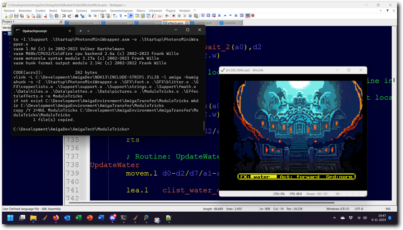
Above: testing the Modulo Tricks program in WinUAE.
The end result is the Modulo Tricks example program, which offers several effects based on manipulating bitplane modulo registers. These effects range from basic forms of manipulation, all the way to more complex effects that also rely on other aspects of the Amiga hardware (such as the Blitter and the Copper's ability to change colours and display shift values).
The first four effects show basic forms of bitplane modulo manipulation. Starting these off is the 'mirror' effect, which vertically mirrors the screen along an ever changing Y coordinate as its axis. Second is the 'repeat' effect, which repeats parts of the top parts of the screen in the bottom part of the screen. Next, there's the 'offset' effect, which skips a number of lines at a changing Y-coordinate. This offsets the screen by that many lines. And lastly, there is the 'stretch' effect, which slowly builds the screen from top to bottom, stretching the bottom line out to the bottom of the screen as it moves. While this is a fairly simple effect to create, it does look quite nice in motion.
Next there are more complex effects, which rely on either more interesting ways to manipulate bitplane modulo values, or add other effects on top. First of these is the 'water' effect, which shows a version of the classic water effect sometimes seen in games and demos.
The 'TV effect' is next, which simulates a CRT screen being turned off (or on). It's a quite fast effect, only lasting a couple of frames, but nonetheless consists of a number of different steps to make it work. The next to last effect included is the 'V-flip' effect, which rotates the screen across the centre Y position in real time. Thanks to the use of bitplane modulo tricks, it can do this without altering any graphics data in memory.
The last effect is the 'scroller' effect, which is my take on a classic 'cracktro' made by Defjam for their cracked version of Turrican 2. I always found that effect rather nice and it was a great deal of fun to figure out how to emulate it using bitplane modulation to freely repeat parts of the screen.
- Basics & Simple Effects
- Advanced Effects
- Memory use, performance and notes
Tab 1
- Basics
- Mirror
- Repeat
- Offset
Tab 1
Manipulating bitplane modulo values using the CPU or Copper can create interesting effects. If you're not familiar with bitplane modulos or how manipulating these values works, a brief description follows. Feel free to skip this tab if you already know this.
The Amiga display hardware can display screen that are less wide than the bitmap they use as source. This is commonly used to support horizontal scrolling through hardware, but also to have extra space around the screen to more easily draw Blitter objects that are partially off the screen. To display screens that are less wide than the source bitmap, the hardware uses two registers called the bitplane modulo registers (BPLMOD1 & BPLMOD2).
There's two of these registers to support Dual Playfield mode, as in this mode either playfield can have a source bitmap with a different width - hence the need for two registers. For Single Playfield mode screens, both of these registers are set to the same value. Since the example program runs in Single Playfield mode, it does this as well.
The value set in these registers tells the Amiga display hardware how many bytes to add to the bitplane pointers after the current line of the screen has been fully displayed. It should be noted here that the display hardware automatically updates the bitplane pointers by adding the number of bytes it has displayed to them after every line. The bitplane modulo represents the value to add on top of this, should this be needed.
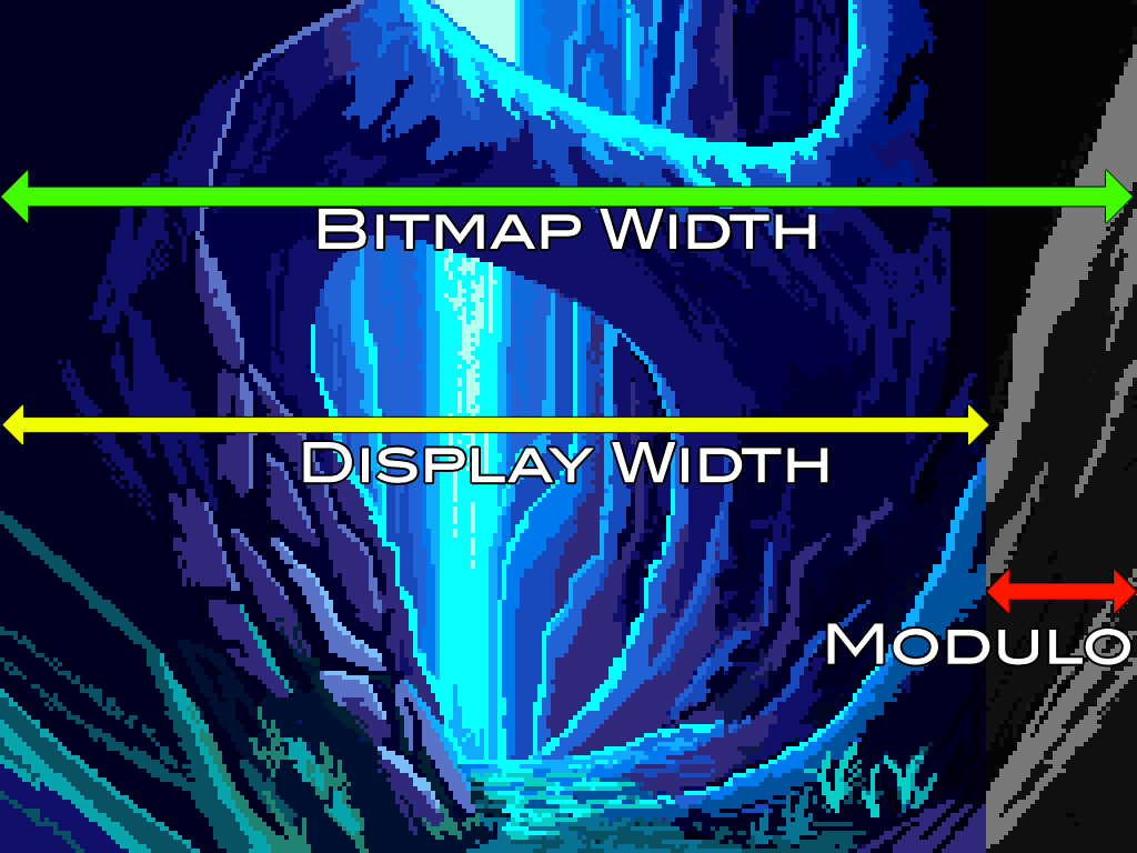
Above: a diagram showing how bitplane modulo values are used
The value needed for correct display on screen therefore depends on how the screen is set up. In a normal (non-interleaved, non-horizontally scrolling) display with a bitmap the same size as the display, the correct bitplane modulo value is zero. For an interleaved screen that does not horizontally scroll and has a bitmap the same size as the display, the value is equal to the number of bytes to reach the next line for each bitplane. That is: number_of_bytes_per_bitplane * (number_of_bitplanes-1). Adding horizontal scrolling or space for bobs that are partially on the screen will change the number further.
However, the bitplane modulo registers are 16-bit signed values. This means they can specify a number of bytes to be added to the bitplane pointers to reach the next display line, or a number of bytes to subtract from the pointers instead. This capability can be used to implement several tricks, such as mirroring or repeating parts of the screen.
The effects shown in the Modulo Tricks program all rely on manipulating these bitplane modulo values.
Tab 2
The 'Mirror' effect uses manipulation of the bitplane modulo registers with the Copper to vertically mirror the screen along a single Y coordinate. In order to make the display more visually interesting, the Y coordinate that is used as the starting point of the effect changes every frame, following a sine wave for smooth animation.
The way it works is by having the Copper wait for the starting point of the line where the effect needs to start and then changing the bitplane modulo registers to reverse the order of lines being drawn. Then, at the end of the screen area reserved for displaying the effect, the bitplane modulos and other values are reset so that the bottom menu bar can be drawn correctly. A minor complication is that the screen used by the example is both interleaved and supports horizontal scrolling. This means the calculation required is a bit different from what would be needed for a non-interleaved screen that does not support horizontal scrolling.
The way it works is by having the Copper wait for the starting point of the line where the effect needs to start and then changing the bitplane modulo registers to reverse the order of lines being drawn. Then, at the end of the screen area reserved for displaying the effect, the bitplane modulos and other values are reset so that the bottom menu bar can be drawn correctly. A minor complication is that the screen used by the example is both interleaved and supports horizontal scrolling. This means the calculation required is a bit different from what would be needed for a non-interleaved screen that does not support horizontal scrolling.
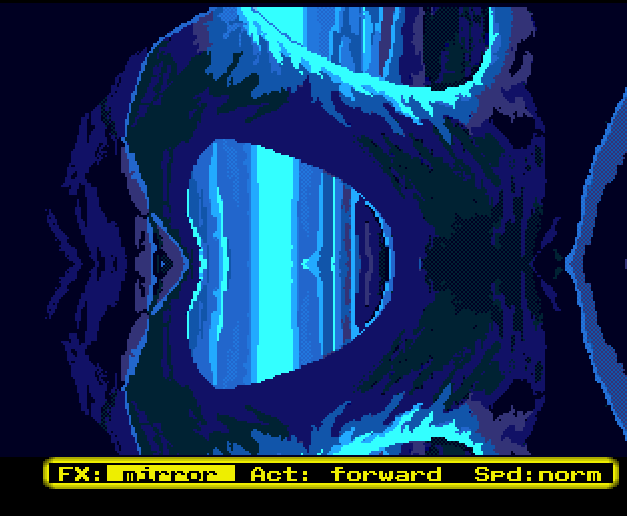
Above: the example program running the 'Mirror' effect.
Here's a step-by-step description of how the new bitplane modulo values are calculated, plus the Copper instructions used to write to the bitplane modulo registers.
The Copper instructions for the mirror effect are:
- To mirror the screen, we need to skip back one line. Memory wise, this is equal to the amount of bytes drawn for a single bitplane per line, plus the distance of one additional line.
- Due to the interleaved nature of the bitmap being used, the distance for one line is equal to the amount of bytes for a single bitplane to reach the next line, multiplied by the number of bitplanes. The effect runs in 4 bitplanes, so a full line amounts to 4 times the bitmap width in bytes.
- Since a single line drawn is equal to display_width/8 bytes, plus 2 bytes for the extra word fetched to support horizontal scrolling, the total offset becomes: -((display_width/8)+2+(bitmap_width_in_bytes*4))
The Copper instructions for the mirror effect are:
	; Wait for desired position, then:
	$0108,-((display_width/8)+2+(bitmap_width_in_bytes*4))
	$010a,-((display_width/8)+2+(bitmap_width_in_bytes*4))
Tab 3
The 'Repeat' effect uses the Copper to manipulate the bitplane modulo registers to repeat a part of the screen further down the screen. In order to make the display more visually interesting, the Y coordinate that is used as the starting point of the effect changes every frame, following a sine wave for smooth animation.
The way it works is by having the Copper wait for the starting point of the line where the effect needs to start and then changing the bitplane modulo registers such that the screen move back half a bitmap's worth of lines. Then, one line later the bitplane modulo registers are changed back to their normal values, so that the screen is drawn normally from that point. Doing this effectively repeats the upper part of the screen to the lower part. A minor complication is that the screen used by the example is both interleaved and supports horizontal scrolling. This means the calculation required is a bit different from what would be needed for a non-interleaved screen that does not support horizontal scrolling.
The way it works is by having the Copper wait for the starting point of the line where the effect needs to start and then changing the bitplane modulo registers such that the screen move back half a bitmap's worth of lines. Then, one line later the bitplane modulo registers are changed back to their normal values, so that the screen is drawn normally from that point. Doing this effectively repeats the upper part of the screen to the lower part. A minor complication is that the screen used by the example is both interleaved and supports horizontal scrolling. This means the calculation required is a bit different from what would be needed for a non-interleaved screen that does not support horizontal scrolling.
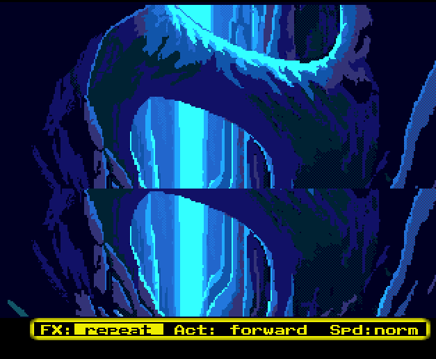
Above: the example program running the 'Repeat' effect.
Here's a step-by-step description of how the new bitplane modulo values are calculated, plus the Copper instructions used to write to the bitplane modulo registers.
The Copper instructions for the repeat effect are:
- To repeat a number of lines of the buffer, the modulo should be equal to the total distance to those lines, minus the amount of bytes drawn this line.
- Due to the interleaved nature of the bitmap being used, this distance is equal to the amount of bytes for a single bitplane to reach the next line, multiplied by the number of bitplanes, multiplied by the number of lines to skip.
- Since this effect repeats part of the screen, the distance should be negative.
- Including the 2 bytes for the extra word fetched to support horizontal scrolling, this leads to a total of: -(bitmap_width_in_bytes*depth*y_distance)-(display_width/8)-2
The Copper instructions for the repeat effect are:
	; Wait for desired position, then:
	$0108,-(bitmap_width_in_bytes*4*112)-(display_width/8)-2
	$010a,-(bitmap_width_in_bytes*4*112)-(display_width/8)-2

	; Wait for next line, then:
	$0108,<<standard bitplane modulo>>
	$010a,<<standard bitplane modulo>>
Tab 4
The 'Offset' effect uses the Copper to manipulate the bitplane modulo registers to skip a part of the bitmap while showing it to the screen, effectively offsetting the display by a number of lines from the Y coordinate at which the offset is done. In order to make the display more visually interesting, the Y coordinate that is used as the starting point of the effect changes every frame, following a sine wave for smooth animation.
The way it works is by having the Copper wait for the starting point of the line where the effect needs to start and then changing the bitplane modulo registers such that the screen skips a number of lines forward in the bitmap. Then, one line later the bitplane modulo registers are changed back to their normal values, so that the screen is drawn normally from that point. Doing this effectively skips part of the source bitmap while the image is displayed. A minor complication is that the screen used by the example is both interleaved and supports horizontal scrolling. This means the calculation required is a bit different from what would be needed for a non-interleaved screen that does not support horizontal scrolling.
The way it works is by having the Copper wait for the starting point of the line where the effect needs to start and then changing the bitplane modulo registers such that the screen skips a number of lines forward in the bitmap. Then, one line later the bitplane modulo registers are changed back to their normal values, so that the screen is drawn normally from that point. Doing this effectively skips part of the source bitmap while the image is displayed. A minor complication is that the screen used by the example is both interleaved and supports horizontal scrolling. This means the calculation required is a bit different from what would be needed for a non-interleaved screen that does not support horizontal scrolling.
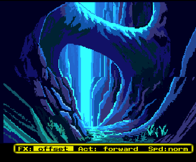
Above: the example program running the 'Offset' effect.
Here's a step-by-step description of how the new bitplane modulo values are calculated, plus the Copper instructions used to write to the bitplane modulo registers.
The Copper instructions for the offset effect are:
- To offset the buffer by a number of lines, the modulo should be equal to the total distance to those lines, minus the amount of bytes drawn this line.
- Due to the interleaved nature of the bitmap being used, this distance is equal to the amount of bytes for a single bitplane to reach the next line, multiplied by the number of bitplanes, multiplied by the number of lines to skip.
- Including the 2 bytes for the extra word fetched to support horizontal scrolling, this leads to a total of: (bitmap_width_in_bytes*depth*y_distance)-(display_width/8)-2
The Copper instructions for the offset effect are:
	$0108,(bitmap_width_in_bytes*4*16)-(display_width/8)-2
	$010a,(bitmap_width_in_bytes*4*16)-(display_width/8)-2

	; Wait for next line, then:
	$0108,<<standard bitplane modulo>>
	$010a,<<standard bitplane modulo>>
Tab 2
- Stretch
- Water
- TV
- V-Flip
- Scroller
Tab 1
The 'Stretch' effect uses the Copper to manipulate the bitplane modulo registers to continually repeat the same line of the bitmap down the screen, effectively stretching the line shown at the Y coordinate being used for the effect down the rest of the display. In order to make the display more visually interesting, the Y coordinate that is used as the starting point of the effect changes every frame, following a sine wave for smooth animation.
The way it works is by having the Copper wait for the starting point of the line where the effect needs to start and then changing the bitplane modulo registers such that the screen skips back to the start of the current line being displayed from the bitmap. Then, at the end of the screen area reserved for displaying the effect, the bitplane modulos and other values are reset so that the bottom menu bar can be drawn correctly. A minor complication is that the screen used by the example is both interleaved and supports horizontal scrolling. This means the calculation required is a bit different from what would be needed for a non-interleaved screen that does not support horizontal scrolling.
The way it works is by having the Copper wait for the starting point of the line where the effect needs to start and then changing the bitplane modulo registers such that the screen skips back to the start of the current line being displayed from the bitmap. Then, at the end of the screen area reserved for displaying the effect, the bitplane modulos and other values are reset so that the bottom menu bar can be drawn correctly. A minor complication is that the screen used by the example is both interleaved and supports horizontal scrolling. This means the calculation required is a bit different from what would be needed for a non-interleaved screen that does not support horizontal scrolling.
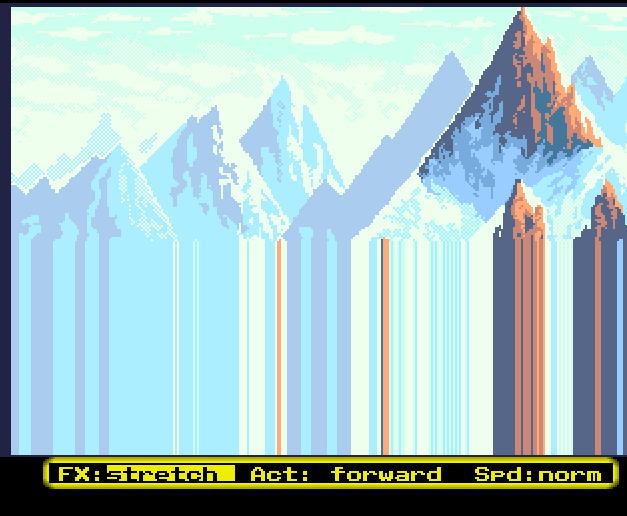
Above: the example program running the 'Stretch' effect.
Here's a step-by-step description of how the new bitplane modulo values are calculated, plus the Copper instructions used to write to the bitplane modulo registers.
The Copper instructions for the stretch effect are:
- To stretch the display, we need to display the same line over and over from the point the stretch effect starts. This can be done by having a modulo value that negates the number of bytes drawn for the current line.
- The number of bytes drawn on a single bitplane per line is equal to display_width/8.
- Then, add the extra word for horizontal scrolling. So the correct value to use is: -(display_width/8)-2
The Copper instructions for the stretch effect are:
	$0108,-(display_width/8)-2
	$010a,-(display_width/8)-2
Tab 2
The 'Water' effect uses a combination of bitplane modulo register manipulation with the Copper, display shift register manipulation with the Copper and changing colours on a scanline-by-scanline basis to create an effect that looks like the bottom part of the screen is made of water, complete with waves and ripples. It dynamically changes all these aspects on a frame-by-frame basis to make the effect more convincing. To increase the length of the effect, the individual parts (bitplane registers, colour changes and horizontal display shift registers) all use different periods before repeating. This causes the effect to look a bit more dynamic than it really is.
For convenience's sake, the values used for each of these aspects are stored in tables that have been generated using a Python script. The Amiga's 68000 is technically fast enough to calculate these things in real time, but reading the values from a table instead simplifies the code a great deal. The use of a higher level language to essentially do the complex part of the code ahead of time decreases development time for these kind of effects by allowing for rapid iterations between different values for the functions used to calculate the various aspects of the effect.
For convenience's sake, the values used for each of these aspects are stored in tables that have been generated using a Python script. The Amiga's 68000 is technically fast enough to calculate these things in real time, but reading the values from a table instead simplifies the code a great deal. The use of a higher level language to essentially do the complex part of the code ahead of time decreases development time for these kind of effects by allowing for rapid iterations between different values for the functions used to calculate the various aspects of the effect.
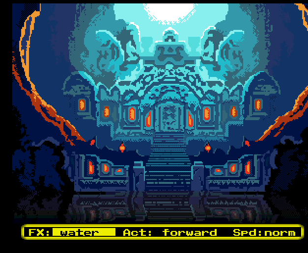
Above: the example program running the 'Water' effect.
Let's go over each of the three aspects (colour changes, horizontal display shift and bitplane modulos) to explain in more detail how the effect works.
Bitplane Modulos
The 'Water' effect essentially combines the 'Mirror' effect with the 'Offset' and 'Repeat' effects to create a vertically mirrored and waving display. The effect starts by mirroring the display and then uses a scaled sine wave to decide for each line of the effect wether to either display the line from the bitmap that is supposed to be displayed, repeat an earlier line or skip to a further line in the bitmap being displayed.
Each new line moves forward in the sine function one step. Since there are 32 lines, each step consists of moving forward in the sine function by 1/32 * (ending_angle - starting_angle) degrees. Between frames, the starting and ending angle get updated to seamlessly wave the display.
By choosing the starting angle, ending angle and maximum amplitude in lines, the effect can be changed to be more or less dynamic. The version of the effect as shown here uses a starting angle of 90 degrees, an ending angle of 150 degrees and a maximum amplitude of 4 lines for the first frame. Between frames, the starting and ending angle are changed as follows:
current_starting_angle = current_starting_angle + (frame * 2)
current_ending_angle = current_ending_angle + (frame * 3)
The total number of unique frames generated is 32. These unique frames are then played back according to a sine wave based function to both slow down the display rate to be more pleasing and to move through them in a smooth fashion. In total, this function results in 391 frames of animation to be displayed, one per frame. This ultimately means that the 32 unique frames are displayed over a ~8 second period before cycling back to the start, rather than the ~0.6 seconds they'd take if played back-to-back.
Horizontal display shift
To make the effect more convincing, the 'water' also waves horizontally, with a different horizontal shift for each line of the effect. Like the bitplane modulo changes done for vertical movement, this horizontal movement is also based on a sine wave function. This function is used to decide by how many pixels to shift the lines being displayed.
Each new line moves forward in the sine function one step. Since there are 32 lines, each step consists of moving forward in the sine function by 1/32 * (ending_angle - starting_angle) degrees. Between frames, the starting and ending angle get updated to seamlessly wave the display.
By choosing the starting angle, ending angle and maximum amplitude in pixels, the effect can be changed to be more or less dynamic. The version of the effect as shown here uses a starting angle of 90 degrees, an ending angle of 450 degrees and a maximum amplitude of 2 pixels for the first frame. Between frames, the starting and ending angle are changed as follows:
current_starting_angle = current_starting_angle + 5.625
current_ending_angle = current_ending_angle + 5.625
The total number of unique frames generated is 64. These unique frames are then played back according to a sine wave based function to both slow down the display rate to be more pleasing and to move through them in a smooth fashion. In total, this function results in 256 frames of animation to be displayed, one per frame. This ultimately means that the 64 unique frames are displayed over a ~5 second period before cycling back to the start, rather than the ~1.3 seconds they'd take if played back-to-back.
Colour changes
To add the final touch to the effect, the palette used for the area of the display that is supposed to show water is changed as well. Like the bitplane modulo values for vertical movement and horizontal shift values, the colour changes also animate based on a sine wave function. This function is used to determine a dynamic change in brightness and saturation of the palette on a line-by-line basis.
Each new line moves forward in the sine function one step. Since there are 32 lines, each step consists of moving forward in the sine function by 1/32 * (ending_angle - starting_angle) degrees. Between frames, the starting and ending angle get updated to seamlessly wave the display.
By choosing the starting angle, ending angle, starting brightness, starting saturation, green factor and blue factor, the effect can be changed to be more or less dynamic. The version of the effect as shown here uses a starting angle of 90 degrees, an ending angle of 150 degrees, a starting brightness of 0.8, starting saturation of 0.5, a green factor 1 of and a blue factor of 1.2. Between frames, the starting and ending angle are changed as follows:
current_starting_angle = current_starting_angle + (frame * 2)
current_ending_angle = current_ending_angle + (frame * 3)
The total number of unique frames generated is 8. These unique frames are then played back according to a sine wave based function to both slow down the display rate to be more pleasing and to move through them in a smooth fashion. In total, this function results in 133 frames of animation to be displayed, one per frame. This ultimately means that the 8 unique frames are displayed over a ~2.7 second period before cycling back to the start, rather than the ~0.2 seconds they'd take if played back-to-back.
Tab 3
The 'TV' effect combines multiple instances of the 'Offset' effect with colour palette manipulation, high animation speeds and a second phase just using the Copper to change one colour repeatedly to create an effect that looks like an old style CRT or TV turning off. It rapidly changes the various offsets and colour palette to create a dynamic effect that looks quite nice despite its short duration. Once the display has been shrunk to a single line in the centre, the display is switched to a single line that uses the Copper to change one colour as rapidly as possible to create a final fade out.
In order to make developing the correct values to use for both the palettes and offsets easier, these where generated using Python scripts and stored into tables that were then used by the example program to display the end result. The 68000 in the Amiga would've been able to calculate these all values in real time, but iterating over the many different variants of the effect until I was happy with what it looked like was much, much easier to do by using pre-calculated tables generated by the scripts I made.
Because the effect runs so fast, the example programs waits a few seconds between each repetition of the effect so as to not flash the screen rapidly over and over.
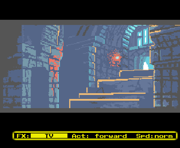
Above: the example program running the 'TV' effect.
Despite the use of pre-calculated values, the Copper list used for this effect is surprisingly complicated. This is because the effect contains various different stages, as well as different sections doing different things in these stages. To understand how the effect works, lets first look at the values generated by the Python scripts: bitplane modulo register values & palettes. The palettes are split up in two sections, namely the palettes for the 'vertically shrinking' phase of the effect and the palettes for the 'horizontal fade' phase of the effect.
Bitplane Modulos
The bitplane modulo registers are dynamically set during the first phase of the effect (vertical shrinking). They're set to skip more and more lines in the bitmap, which in effect shrinks the part of the bitmap that is shown to an ever smaller region. In order to look like the typical CRT/TV effect of the display shrinking rapidly towards the centre Y position of the screen, the bitmap is displayed further and further down towards the centre of the of the screen as this happens.
For a slow effect, shrinking the display like this would need the bitplane modulo registers set every line to allow for a very smooth and gradual shrinking of the display. However, the 'TV' shrinking effect runs so quickly (it takes only 6 frames in total, or 0.12 seconds) that such precision is not required. Instead, there are only 8 lines per frame where the bitplane modulo's are changed to shrink the screen. Because the effect runs so quickly, this is enough to keep the illusion of a smooth but very fast shrinking display work.
However, there are more than 8 bitplane modulo register updates per frame. In order to have the display be free of garbage and add some more parts to the effect to help sell the illusion, more updates are needed. On top of that, after every bitplane modulo register change, the bitplane modulo's must be reset to normal to not skip way too many lines.
In total, there are 21 updates to the bitplane modulo registers per frame:
Each of these 21 updates also have Copper wait instructions to position the shrinking effect correctly
To make the animation of the effect smooth and fast, the number of lines to skip and positions to wait for are calculated using a two-step function: for the first part, the number of lines to skip (and location of positions to wait for) are increased using a quadratic function. This rapidly increases the number of lines to skip (and locations) between each frame. The second part of the function eases out over a few frames to smooth out the animation. This is done using a sine-wave function that moves across 90 degrees for the duration of the ease out section.
A total of 6 frames are generated for this part of the effect. The effect as shown runs this part in real time (so it takes 6 frames, of which 2 are 'ease out' frames). The next part of the effect (the horizontal colour fade) does not rely on bitplane modulo values.
Colour palettes (vertical shrinking phase)
The palettes used for the effect are set dynamically. During the vertical shrinking phase of the effect, there are three palettes in use. At the top and bottom of the screen, the palette is set to contain black for every colour register used. Directly below (and above) the black sections, the second palette is used. This palette starts out as black for every colour register used and rapidly fades to full white over the duration of this phase of the effect.
This 'white bar' is maintained over a certain number of lines before the third and final palette is used. The third and final palette starts out with the full palette for the image being shown and rapidly fades to fully white over the duration of this phase of the effect. below the shrinking image, the 'white bar' is repeated, followed by black.
Because there's only three palettes (and one is just an array of zeroes), the setup is simpler than for the bitplane modulos being set. For both the 'white bar' and the picture palettes, the same algorithm is used. The colours are faded from their starting palette (all black for the 'white bar' and the palette for the picture being shown) to a target palette which has all colours set to white. The colour fade uses a fade factor, which determines how close to the target palette to fade. This fade factor is increased using a quadratic function, which causes the colour change to accelerate as the effect progresses.
The example program then updates the Copper list to have the correct palette for the frame being shown. Since there's only 6 frames for this phase of the effect, each of the 6 entries per palette is simply 'played back' one after the other.
Colour palette (horizontal fading phase)
During the horizontal fading phase, the colour palette starts at white and then rapidly fades out, starting at the edges and moving towards the centre. This simulates the final fade out that many CRT's and old TV's had. Instead of using an image with many colours all set to white, the final fade uses only one colour register and uses the Copper to change its value as often as it can. This effectively causes the display to have pixels that are 8 normal low res pixels wide. However, due to the high speed of the effect, this large pixel size is not as noticeable as it otherwise would be.
In total, there are 45 of these 8x1 pixels, covering 360 pixels. This is enough to fill all of the screen's width, including the overscan/border regions. As the effect progresses, the white colour pixels get faded out using a quadratic function, meaning the fade-out will happen faster and faster as time progresses. To make the fade out look more natural, colours furthest from the midpoint are affected most by the fade, while the midpoint itself is affected the least.
Bitplane Modulos
The bitplane modulo registers are dynamically set during the first phase of the effect (vertical shrinking). They're set to skip more and more lines in the bitmap, which in effect shrinks the part of the bitmap that is shown to an ever smaller region. In order to look like the typical CRT/TV effect of the display shrinking rapidly towards the centre Y position of the screen, the bitmap is displayed further and further down towards the centre of the of the screen as this happens.
For a slow effect, shrinking the display like this would need the bitplane modulo registers set every line to allow for a very smooth and gradual shrinking of the display. However, the 'TV' shrinking effect runs so quickly (it takes only 6 frames in total, or 0.12 seconds) that such precision is not required. Instead, there are only 8 lines per frame where the bitplane modulo's are changed to shrink the screen. Because the effect runs so quickly, this is enough to keep the illusion of a smooth but very fast shrinking display work.
However, there are more than 8 bitplane modulo register updates per frame. In order to have the display be free of garbage and add some more parts to the effect to help sell the illusion, more updates are needed. On top of that, after every bitplane modulo register change, the bitplane modulo's must be reset to normal to not skip way too many lines.
In total, there are 21 updates to the bitplane modulo registers per frame:
- 2 updates at the top of each frame to set the modulo register values for the top section of the screen that is either black or fading to white
- 1 update after that to set the correct modulo values for the start of the picture
- 16 updates after that to deal with the actual shrinking of the screen (split into updates to skip a number of lines and updates to reset to normal display)
- 2 updates at the bottom of each frame to set the modulo register values for the bottom section of the screen that is either fading to white or black
Each of these 21 updates also have Copper wait instructions to position the shrinking effect correctly
To make the animation of the effect smooth and fast, the number of lines to skip and positions to wait for are calculated using a two-step function: for the first part, the number of lines to skip (and location of positions to wait for) are increased using a quadratic function. This rapidly increases the number of lines to skip (and locations) between each frame. The second part of the function eases out over a few frames to smooth out the animation. This is done using a sine-wave function that moves across 90 degrees for the duration of the ease out section.
A total of 6 frames are generated for this part of the effect. The effect as shown runs this part in real time (so it takes 6 frames, of which 2 are 'ease out' frames). The next part of the effect (the horizontal colour fade) does not rely on bitplane modulo values.
Colour palettes (vertical shrinking phase)
The palettes used for the effect are set dynamically. During the vertical shrinking phase of the effect, there are three palettes in use. At the top and bottom of the screen, the palette is set to contain black for every colour register used. Directly below (and above) the black sections, the second palette is used. This palette starts out as black for every colour register used and rapidly fades to full white over the duration of this phase of the effect.
This 'white bar' is maintained over a certain number of lines before the third and final palette is used. The third and final palette starts out with the full palette for the image being shown and rapidly fades to fully white over the duration of this phase of the effect. below the shrinking image, the 'white bar' is repeated, followed by black.
Because there's only three palettes (and one is just an array of zeroes), the setup is simpler than for the bitplane modulos being set. For both the 'white bar' and the picture palettes, the same algorithm is used. The colours are faded from their starting palette (all black for the 'white bar' and the palette for the picture being shown) to a target palette which has all colours set to white. The colour fade uses a fade factor, which determines how close to the target palette to fade. This fade factor is increased using a quadratic function, which causes the colour change to accelerate as the effect progresses.
The example program then updates the Copper list to have the correct palette for the frame being shown. Since there's only 6 frames for this phase of the effect, each of the 6 entries per palette is simply 'played back' one after the other.
Colour palette (horizontal fading phase)
During the horizontal fading phase, the colour palette starts at white and then rapidly fades out, starting at the edges and moving towards the centre. This simulates the final fade out that many CRT's and old TV's had. Instead of using an image with many colours all set to white, the final fade uses only one colour register and uses the Copper to change its value as often as it can. This effectively causes the display to have pixels that are 8 normal low res pixels wide. However, due to the high speed of the effect, this large pixel size is not as noticeable as it otherwise would be.
In total, there are 45 of these 8x1 pixels, covering 360 pixels. This is enough to fill all of the screen's width, including the overscan/border regions. As the effect progresses, the white colour pixels get faded out using a quadratic function, meaning the fade-out will happen faster and faster as time progresses. To make the fade out look more natural, colours furthest from the midpoint are affected most by the fade, while the midpoint itself is affected the least.
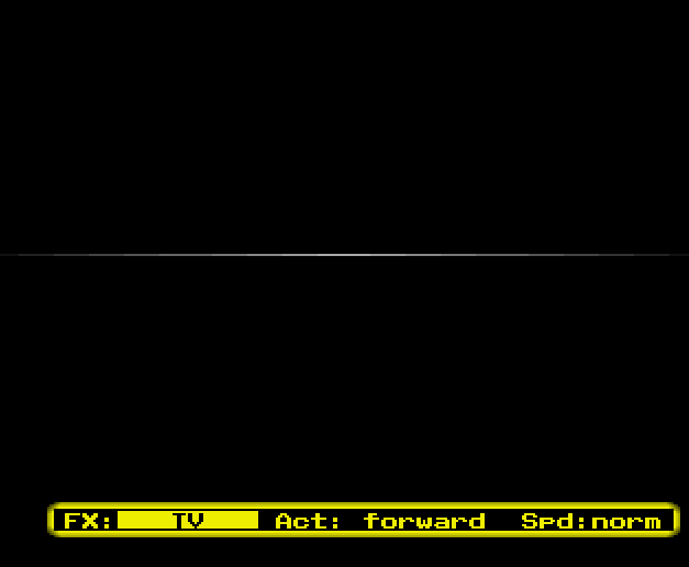
Above: the example program during the horizontal fading part of the 'TV' effect.
To calculate the how much to fade each pixel, the following calculation is done based on the fade factor for the current frame:
distance = abs(colour_counter-mid_point)
if distance != 0:
   distance_factor = (distance/mid_point)
else:
   distance_factor = 0
corrected_fade_factor = fade_factor + ((1 - fade_factor) * distance_factor)
The higher the fade factor, the closer the colour will be to black.
The horizontal fade out effect has a duration of 8 frames, or 0,16 seconds and end with all pixels coloured black.
Copperlist Structure
Next, lets look at the Copper list setup for the 'TV' effect. First the overal structure, then how both of the effect phases (vertical shrinking and horizontal fading, respectively) work.
The Copperlist for the 'TV' effect consists of a generic part and the effect specific parts. The generic part sets up COP2LCL & COP2LCH at the start and jumps back to the main Copperlist at the end. This poses a problem for the effect specific parts, as they too need to use the Copper's ability to jump around in the Copperlist. To get around this, the effect specific parts overwrite the COP2LCL & COP2LCH values as needed. This is a somewhat messy approach and could've been done in a neater way. However, for simplicity in the part of the program that allows for effect selection and activation, all effects use the same method - the program assumes it can set the return address for the effect at the very start of it's effect specific Copperlist and assumes the effect specific Copperlist jumps back to that address when it's done with the effect.
In the Copperlist for the effect, the generic part looks as follows:
clist_tv
	dc.w	$0084,$0000					; Copperlist 2 pointer
	dc.w	$0086,$0000

	dc.w	$ffdf,$fffe					; PAL area wait

	; Jump past entire effect (optional)
tv_cop2jmp0
	dc.w	$008a,$0000					; Copperlist 2 jump or NO-OP

tv_cop2lc1
	dc.w	$0084,$0000					; Copperlist 2 pointer
	dc.w	$0086,$0000

	dc.w	$ffdf,$fffe					; PAL area wait

	; Jump past (parts of) effect (optional)
tv_cop2jmp1
	dc.w	$008a,$0000					; Copperlist 2 jump or NO-OP
Note: some comments have been omitted to save space, the source code contains additional explanation of what is going on.
The first Copperlist 2 pointer change is the one expected by the part of the program that allows for effect selection and activation. The PAL area wait that follows is either kept as a PAL area wait, or overwritten by a Copper NO-OP ($01fe,) if it is not needed. Then, the Copperlist either ends (in which case tv_cop2jmp0 is kept as a COP2JMP), or continues (in which case tv_cop2jmp0 is overwritten by a NO-OP).
If the Copperlist continues, the next step is to set up the Copperlist 2 pointer (tv_cop2lc1) to either skip parts of the effect as needed, or set to the very next Copper instruction. Next up, there is a PAL area wait in case this is needed. If it isn't, it is replaced by a NO-OP. Lastly, at tv_cop2jmp1 the COP2JMP is either done or replaced by a NO-OP.
In retrospect, I believe that this part of the Copperlist (as well as some other COP2LCH/COP2LCL/COP2JMP manipulation in later parts) might have been better done in a different way, which would've been less confusing than the current setup. This would've required some tweaks to the main program code and changing the way the effect deals with the difference between showing an unaltered image, a frame of the vertical shrinking phase or a frame of the horizontal fade section.
Vertical Shrinking Copperlist Segment
The vertical shrinking part of the Copperlist consists of 6 distinct sections:
Since the starting section can be set in the generic part of the Copperlist for this effect, the first 3 steps do not change the COP2LCH/COP2LCL value and contain no COP2JMP writes. Similarly, because the first 3 steps happen at the top of the screen, they do not contain any PAL area wait either.
After step 4, 5 and 6 however, COP2LCH/COP2LCL are updated, a PAL area wait is included and a write to COP2JMP is present. These are dynamically changed or set to Copper NO-OP instructions as needed. Generally, these blocks of Copper instructions all look like this:
The first Copperlist 2 pointer change is the one expected by the part of the program that allows for effect selection and activation. The PAL area wait that follows is either kept as a PAL area wait, or overwritten by a Copper NO-OP ($01fe,
If the Copperlist continues, the next step is to set up the Copperlist 2 pointer (tv_cop2lc1) to either skip parts of the effect as needed, or set to the very next Copper instruction. Next up, there is a PAL area wait in case this is needed. If it isn't, it is replaced by a NO-OP. Lastly, at tv_cop2jmp1 the COP2JMP is either done or replaced by a NO-OP.
In retrospect, I believe that this part of the Copperlist (as well as some other COP2LCH/COP2LCL/COP2JMP manipulation in later parts) might have been better done in a different way, which would've been less confusing than the current setup. This would've required some tweaks to the main program code and changing the way the effect deals with the difference between showing an unaltered image, a frame of the vertical shrinking phase or a frame of the horizontal fade section.
Vertical Shrinking Copperlist Segment
The vertical shrinking part of the Copperlist consists of 6 distinct sections:
- set the palette to black
- set the palette to the 'white' value for the current frame
- set the palette to the values for the current frame of the vertical shrink effect
- vertically shrink the image
- set the palette to the 'white' value for the current frame
- set the palette to black
Since the starting section can be set in the generic part of the Copperlist for this effect, the first 3 steps do not change the COP2LCH/COP2LCL value and contain no COP2JMP writes. Similarly, because the first 3 steps happen at the top of the screen, they do not contain any PAL area wait either.
After step 4, 5 and 6 however, COP2LCH/COP2LCL are updated, a PAL area wait is included and a write to COP2JMP is present. These are dynamically changed or set to Copper NO-OP instructions as needed. Generally, these blocks of Copper instructions all look like this:
	; Set COP2LCH/L
tv_cop2lc2
	dc.w	$0084,$0000					; Copperlist 2 pointer
	dc.w	$0086,$0000

	dc.w	$ffdf,$fffe					; PAL area wait or NO-OP

	; Jump past (parts of) effect (optional)
tv_cop2jmp2
	dc.w	$008a,$0000					; Copperlist 2 jump or NO-OP
At the end of step 6, the Copper jumps back to the main Copperlist to display the menu/status bar at the bottom of the screen.
Step 4 itself is special, in that it both contains the bitplane modulo changes to shrink the image and an optional PAL area wait. This is needed because the exact location of the PAL area wait in the Copper list will change as the image shrinks. The Copper code to actually shrink the image is surprisingly simple and looks like this:
Step 4 itself is special, in that it both contains the bitplane modulo changes to shrink the image and an optional PAL area wait. This is needed because the exact location of the PAL area wait in the Copper list will change as the image shrinks. The Copper code to actually shrink the image is surprisingly simple and looks like this:
REPT 8
	dc.w	$01fe,$fffe							; PAL area wait or NO-OP
	dc.w	$2c01,$fffe							; Wait position
	dc.w	$0108,(buffer_modulo*4*lines_to_skip)-(display_width/8)-2	; BPL1MOD
	dc.w	$010a,(buffer_modulo*4*lines_to_skip)-(display_width/8)-2	; BPL2MOD
	dc.w	$2c41,$fffe							; Wait position
	dc.w	$0108,standard_modulo						; BPL1MOD
	dc.w	$010a,standard_modulo						; BPL2MOD
ENDR
Note that the Copper code here makes use of the way bitplane modulo changes work. They only get updated once per line, prior to the first fetch of the bitplane data. This means that changing them after the bitplane fetch has started will only impact the next line.
Horizontally Fading Copperlist Segment
Compared to the vertical fading part of the effect, the horizontal fading segment is much simpler. It simply sets up a 1-line, 1-bitplane screen with both colours initially set to black. Then it waits for the centre line of the display and repeats 45 Copper writes to colour 0. Initially these 45 writes are all set to white and as the effect progresses they rapidly fade out to black.
After this, colour 0 is reset to black. Then COP2LCH/COP2LCL get set, a PAL area wait is done and COP2JMP is written to in order to jump back to the main Copperlist.
The only interesting part of the Copperlist is that it sets up the display to continually repeat the single empty line of bitmap data that is reserved in memory for use during this effect. It does this by using the bitplane modulo values to repeat a line indefinitely, similar to how the 'Stretch' effect works:
	dc.w	$0108,-(display_width/8)-2	; BPL1MOD
	dc.w	$010a,-(display_width/8)-2	; BPL2MOD
Tab 4
The 'V-Flip' effect combines the 'Offset' effect and 'Mirror' effect and uses them to update the bitplane modulo values on every single line of the visible image. This in turn is combined with a cosine function to generate an orientation (either upright or upside down) and calculate how many lines of the image should be drawn for the current frame. This is then spread out over the bitplane modulo updates to display an image, that starts upright and transitions to being upside down and back again to being upright.
Because the image's orientation and size are dependent on a cosine wave, the animation is smooth and the vertical flip looks like it's rotating the entire image slowly. The calculations for setting up each frame are done in real time, as using a table to do so would've required a very big table for a relatively simple calculation. Since the 68000 is more than fast enough to do the required multiplications and the exact required calculations are simple to code in assembly, this works out well.
Because the image's orientation and size are dependent on a cosine wave, the animation is smooth and the vertical flip looks like it's rotating the entire image slowly. The calculations for setting up each frame are done in real time, as using a table to do so would've required a very big table for a relatively simple calculation. Since the 68000 is more than fast enough to do the required multiplications and the exact required calculations are simple to code in assembly, this works out well.
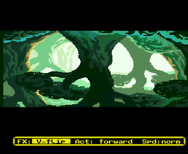
Above: the example program running the 'V-flip' effect.
Despite needing many entries, the Copperlist for the V-flip effect is relatively simple. It consists of setting up an all-black palette, and waiting to the first line of the screen the image being flipped is actually visible. Then, it sets up the correct palette for the image being shown, and sets up both COP1LCH & COP1LCL and COP2LCH & COP2LCL. The first is being used at a jump point into a list of Copper instructions that change the bitplane modulos. The second is used as the point where the effect should jump to after it has displayed all currently visible lines of the image as it's being flipped.
The list of Copper instructions that change the bitplane modulos is being dynamically updated between frames to show the correct image for the current frame of the effect. It consists of 224 entries, though in almost all frames (far) fewer are being used. The Copper instructions for this part look like this:
The list of Copper instructions that change the bitplane modulos is being dynamically updated between frames to show the correct image for the current frame of the effect. It consists of 224 entries, though in almost all frames (far) fewer are being used. The Copper instructions for this part look like this:
		; Flip effect
		REPT 224
.vert_val	SET	($2c+REPTN)&$ff				; Calculate current line
			dc.w	(.vert_val<<8)|$db,$fffe	; Wait for start of each line
			dc.w	$0108,standard_modulo		; BPL1MOD
			dc.w	$010a,standard_modulo		; BPL2MOD
			dc.w	$01fe,$0000			; NO-OP or COP2JMP
		ENDR
In this list of Copper instructions, the bitplane modulo values get overwritten with new ones between frames and the NO-OP gets replaced by a COP2JMP write when the final line has been displayed.
After this, there is an optional PAL-area wait instruction (that is either executed or skipped based on the height of the image this frame) and setting all palette colours to black to hide any garbage which would otherwise be visible. After that, the Copperlist jumps back to main Copperlist to display the menu/status bar.
Calculating the bitplane modulos to use is done as follows:
Since the image shrinks and grows, the remaining Copperlist entries (before and after the effect region for the current frame) as set to simply repeat the last line shown. Because the palette in these regions of the screen is set to all black, this repetition is not visible.
*) Both the sine and cosine functions contained in the program use a 16.16 fixed point, 1/4 degree accurate, 360 degree sine wave table as their source.
After this, there is an optional PAL-area wait instruction (that is either executed or skipped based on the height of the image this frame) and setting all palette colours to black to hide any garbage which would otherwise be visible. After that, the Copperlist jumps back to main Copperlist to display the menu/status bar.
Calculating the bitplane modulos to use is done as follows:
- First, the code uses the current frame of the effect as the angle to use and calls a routine that returns a fixed point number representing the cosine value for that angle*
- This number is then multiplied by 224, which is the number of lines the image uses on the screen
- The absolute result of this is the number of lines the image should be displayed on for this frame, the sign is kept to know whether to start at the top of the image or at the bottom
- The number of lines to display is used to determine how many lines to skip per line shown. This is a fixed point number in order to support fractional results
- For each line to display, the modulo is calculated based on the number of lines to skip per line as a simple multiplication of the width in bytes of the bitmap (taking into account the fact that the screen is interleaved) and the number of lines to skip. The number of lines to skip is first converted to an integer for this multiplication.
- The modulo is corrected for the number of bytes already displayed at this point by subtracting (display_width/8)+2.
- Between lines, any remainder of the conversion to integer is kept and added to the number of lines to skip for next line to display
Since the image shrinks and grows, the remaining Copperlist entries (before and after the effect region for the current frame) as set to simply repeat the last line shown. Because the palette in these regions of the screen is set to all black, this repetition is not visible.
*) Both the sine and cosine functions contained in the program use a 16.16 fixed point, 1/4 degree accurate, 360 degree sine wave table as their source.
Tab 5
The 'Scroller' effect combines the 'Repeat' effect with re-using the same monochrome bitmap on multiple bitplanes, Copper colour reloading, horizontal hardware scrolling and the Blitter to generate a screen filled with vertically waving, horizontally scrolling text in many colours.
On the Amiga, drawing individual pixels is a lot slower than drawing rectangular blocks of pixels. In particular, drawing pixels from left to right one at a time is extremely inefficient compared to writing many pixels from left to right in a single block based operation. This poses a problem, because vertically waving text uses a different offset in the character being drawn for each horizontal pixel. Unless the font is pre-processed to contain every single animation frame possible for the text to be drawn, drawing such a vertically waving font is by necessity extremely inefficient.
However, creating a pre-rendered font for the waving text is not feasible due to the excessive memory requirements. Each character, at a basic size like 8x8 or 16x16 pixels, would need to accommodate every possible vertical position within the sine wave across different frames. Because the sine wave effect must appear continuous from the left to the right edge of the screen, every character must align seamlessly with its neighbours in any given frame. This necessitates storing numerous variations for each character to cover all wave positions, dramatically increasing the memory needed beyond practical limits.
Because of this, there is no choice but to draw the text pixel-by-pixel. There's a small improvement in performance that can be gained by drawing an entire vertical strip of 1 pixel wide using the blitter in one Blit, rather than using separate writes for each pixel, but overall the Blitter cost for drawing this on a full screen, even if in one bitplane, would be far too much for the system to handle*.
Another challenge is calculating the per-pixel offset for each horizontal position. This requires multiplying the sine wave result for the current angle by the number of bytes per line of the bitmap being blit to. Since this is not a power of two, the result would be doing 336 fixed point multiplications, which would slow the effect down from the 50Hz update goal. To fix this, the scroller uses a pre-calculated sine-wave table that is already multiplied by the number of bytes per line of the bitmap being blit to.
*) It should be pointed out that the way the example program uses Blitter waits is not very optimal in this case, as the effect uses a very large number of individual blits each frame. It would've been much more efficient to run the blitting code from Chip RAM and setting BLTHOG to 1 (so that the Blitter would not be interrupted by the CPU during the Blitter wait). However, there is enough time to do it this way and I felt that moving this specific code to Chip RAM might have been less clear in intent than having explicit Blitter Waits being done.
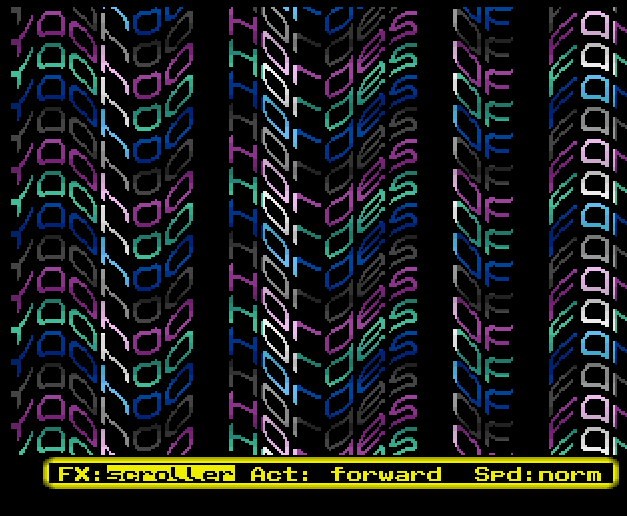
Above: the example program running the 'Scroller' effect.
To make the effect work on a full screen, the example makes use of bitplane modulo manipulation to vertically repeat the same strip of text over and over - effectively turning a 32 pixel tall effect into a 224 pixel tall effect. The way this works is as follows: every frame, one line of the text gets rendered out by the Blitter, with all the vertical waves required. This line is positioned horizontally onto the screen by using the hardware scroll registers. This allows for a line of text to scroll across the screen smoothly, while waving vertically according to the sine wave.
To show more than one line on the screen, the Copper sets the bitplane pointers for bitplanes 1, 2, 3 and 4 to the same bitmap, but at different vertical offsets. Each bitplane is offset from the next by 16 lines, which causes four copies of the text to show on screen, offset by 16 extra lines each. The Copper then updates the bitplane modulo registers at strategic points to move the entire 64 pixel block down by 64 pixels. This repeats the four lines over and over until the entire screen is filled.
In the program's code, this is done using conditional assembly, which selects which bitplane modulo registers need to be updated based on the scanline the Copperlist is currently updating. The code to do so consists of two parts: one part to set up variables that get set to 1 whenever the bitplane modulos need to be updated and one part that updates the actual bitplane modulos if the variables are set to 1.
The part setting the variables looks as follows:
		REPT 224
			; Set initial values for testing if modulo change is needed
.block_one		SET 0
.block_two		SET 0
.block_one_test	SET	REPTN-$1f
.block_two_test	SET	REPTN-$3f
.block_two_test	SET	REPTN-$3f

			; Test if modulo change block one needs to trigger
			IF .block_one_test&$ffc0=.block_one_test
.block_one		SET 1
			ENDIF

			; Test if modulo change block two needs to trigger
			IF .block_two_test&$ffc0=.block_two_test
.block_two		SET 1
			ENDIF

<....>
		ENDR
The part that updates the bitplane modulos looks as follows (and is part of the same REPT/ENDR loop seen above):
			IF .block_one=1
			; Repeat 64 pixel block for bitplanes 1 & 3
.vert_val		SET	($2c+REPTN)&$ff
				dc.w	(.vert_val<<8)|$c7,$fffe		; Wait
				dc.w	$0108,-(buffer_modulo*63)-(display_width/8)-2
.vert_val		SET .vert_val+1
				dc.w	(.vert_val<<8)|$01,$fffe		; Wait
				dc.w	$0108,fg_scr_mod			; Scroller modulo
			ENDIF

			IF .block_two=1
				; Repeat 64 pixel block for bitplanes 2 & 4
.vert_val		SET	($2c+REPTN)&$ff
				dc.w	(.vert_val<<8)|$c7,$fffe		; Wait
				dc.w	$010a,-(buffer_modulo*63)-(display_width/8)-2
.vert_val		SET .vert_val+1
				dc.w	(.vert_val<<8)|$01,$fffe		; Wait
				dc.w	$010a,fg_scr_mod			; Scroller modulo
			ENDIF
In order to make the effect look better, the Copper is also used to reload the colour registers multiple times per frame. Technically the colour choices made here could've changed such that every line of text has it's own colour set, but the effect this is based on only uses 4 colour gradients, so I decided to also use that many. Further improving the look & feel of the effect is the use of the 5th bitplane as a set of alternative colours for each bitplane, which is what causes the 'bright' colours seen on several horizontal positions. These blocks could've also scrolled along with the text, but I had spend quite a bit of time on the program by the time I got to this point and therefore left them static instead.
The Copper colour reloading is done by updating the 8 colours used by the effect every 4 scanlines. The colours used by the effect were generated using a Python script, which uses linear interpolation to fade the colours between a starting and ending colour.
The Copper colour reloading is done by updating the 8 colours used by the effect every 4 scanlines. The colours used by the effect were generated using a Python script, which uses linear interpolation to fade the colours between a starting and ending colour.
Tab 3
- Memory use
- Performance
- Notes
Tab 1
Like all of my example programs, the program allocates all required memory for all the effects combined in one go. It also contains all pictures, tables and other data directly in the executable. This makes the executable quite large (though it does run on a 512KB setup) and makes it hard to see the individual costs for these effects.
The picture data used by the program makes up the bulk of the executable size. Each picture used requires 38400 bytes of Chip RAM, plus a small amount of memory to store the palette. The next biggest element are the pre-calculated tables used by some of the effects. Lastly, the font used by the 'Scroller' effect and the internal bitmaps for the 'TV' and 'Scroller' effects also use some Chip RAM.
Some memory is also allocated at runtime, namely the buffers used for the display.
Most of the effects are quite lightweight in terms of memory requirements, though a few do use more memory - either out of convenience (i.e. by storing pre-calculated tables), or out of necessity (i.e. needing more buffers or a much larger Copperlist). Let's go over the memory requirements for each of the effects.
For the purposes of memory calculations the memory requirements for the standard part of the Copperlist and the display buffer will not be counted, as they'd be required for a simple display regardless. Memory needed by the example program to run it's menu system and other non-effect elements will likewise not be counted.
The simple effects
The four simple effects ('Mirror','Repeat','Offset','Stretch') use the least amount of memory. Apart from the basic memory requirements to have the display working (i.e. standard Copperlist & display buffer), they only require the use of the sine table and a small Copperlist.
The sine table uses 5760 bytes of RAM (of any type), the Copperlist for these effects are essentially identical apart from the bitplane modulo settings and use a maximum of 48 bytes of Chip RAM each.
Total RAM use: <=48 bytes of Chip RAM, 5760 bytes of any RAM.
The 'Water' effect
The 'Water' effect uses a number of pre-calculated tables and a fairly large Copperlist, as apart from setting new bitplane modulos and horizontal shifts each line of the effect, it also sets all colour registers for every line of the effect.
The effect uses 4 tables for bitplane modulos and horizontal shifts and 2 tables for the palettes to use. Combined, these 6 tables use 16580 bytes, of which 8214 bytes are palette data and 8736 bytes are bitplane modulo and horizontal shift data. The Copperlist for the 'Water' effect comes to 2448 bytes in size.
Total RAM use: 2448 bytes of Chip RAM, 16580 bytes of any RAM.
The 'TV' effect
The 'TV' effect uses several pre-calculated tables and a Copperlist, which sets up the various phases of the effect and takes care of the colour reloading. The effect uses 2 palettes for Copper waits and bitplane modulos and 7 tables for palettes to use. Combined, these 9 tables use 1832 bytes, of which 1196 bytes are palette data and 636 bytes are Copper wait/bitplane modulo data. The Copperlist for the 'TV' effect comes to 1000 bytes in size.
In addition, the TV effect uses an extra bitmap, consisting of one empty line. This bitmap uses 48 bytes of memory.
Total RAM use: 1048 bytes of Chip RAM, 1832 bytes of any RAM.
The 'V-Flip' effect
Like the simpler effects, the 'V-flip' effect uses the sine wave table and a Copperlist to run and nothing else. The sine table uses 5760 bytes of RAM (of any type), the Copperlist takes up 3908 bytes.
Total RAM use: 3908 bytes of Chip RAM, 5760 bytes of any RAM.
The 'Scroller' effect
The 'Scroller' effect is unique in that it is the only effect that actually changes pixels in memory. To do so, it uses a Font image, a background image (to set the regions of the screen that use a brighter set of colours), bitmap for the background and two bitmaps to store the resulting scrolling & waving text. On top of that, the effect also uses a Copperlist to reload Palette data and set bitplane modulos, the sine wave table and a table containing the palette to be used.
Total RAM use: 17688 bytes of Chip RAM, 6656 bytes of any RAM.
The picture data used by the program makes up the bulk of the executable size. Each picture used requires 38400 bytes of Chip RAM, plus a small amount of memory to store the palette. The next biggest element are the pre-calculated tables used by some of the effects. Lastly, the font used by the 'Scroller' effect and the internal bitmaps for the 'TV' and 'Scroller' effects also use some Chip RAM.
Some memory is also allocated at runtime, namely the buffers used for the display.
Most of the effects are quite lightweight in terms of memory requirements, though a few do use more memory - either out of convenience (i.e. by storing pre-calculated tables), or out of necessity (i.e. needing more buffers or a much larger Copperlist). Let's go over the memory requirements for each of the effects.
For the purposes of memory calculations the memory requirements for the standard part of the Copperlist and the display buffer will not be counted, as they'd be required for a simple display regardless. Memory needed by the example program to run it's menu system and other non-effect elements will likewise not be counted.
The simple effects
The four simple effects ('Mirror','Repeat','Offset','Stretch') use the least amount of memory. Apart from the basic memory requirements to have the display working (i.e. standard Copperlist & display buffer), they only require the use of the sine table and a small Copperlist.
The sine table uses 5760 bytes of RAM (of any type), the Copperlist for these effects are essentially identical apart from the bitplane modulo settings and use a maximum of 48 bytes of Chip RAM each.
Total RAM use: <=48 bytes of Chip RAM, 5760 bytes of any RAM.
The 'Water' effect
The 'Water' effect uses a number of pre-calculated tables and a fairly large Copperlist, as apart from setting new bitplane modulos and horizontal shifts each line of the effect, it also sets all colour registers for every line of the effect.
The effect uses 4 tables for bitplane modulos and horizontal shifts and 2 tables for the palettes to use. Combined, these 6 tables use 16580 bytes, of which 8214 bytes are palette data and 8736 bytes are bitplane modulo and horizontal shift data. The Copperlist for the 'Water' effect comes to 2448 bytes in size.
Total RAM use: 2448 bytes of Chip RAM, 16580 bytes of any RAM.
The 'TV' effect
The 'TV' effect uses several pre-calculated tables and a Copperlist, which sets up the various phases of the effect and takes care of the colour reloading. The effect uses 2 palettes for Copper waits and bitplane modulos and 7 tables for palettes to use. Combined, these 9 tables use 1832 bytes, of which 1196 bytes are palette data and 636 bytes are Copper wait/bitplane modulo data. The Copperlist for the 'TV' effect comes to 1000 bytes in size.
In addition, the TV effect uses an extra bitmap, consisting of one empty line. This bitmap uses 48 bytes of memory.
Total RAM use: 1048 bytes of Chip RAM, 1832 bytes of any RAM.
The 'V-Flip' effect
Like the simpler effects, the 'V-flip' effect uses the sine wave table and a Copperlist to run and nothing else. The sine table uses 5760 bytes of RAM (of any type), the Copperlist takes up 3908 bytes.
Total RAM use: 3908 bytes of Chip RAM, 5760 bytes of any RAM.
The 'Scroller' effect
The 'Scroller' effect is unique in that it is the only effect that actually changes pixels in memory. To do so, it uses a Font image, a background image (to set the regions of the screen that use a brighter set of colours), bitmap for the background and two bitmaps to store the resulting scrolling & waving text. On top of that, the effect also uses a Copperlist to reload Palette data and set bitplane modulos, the sine wave table and a table containing the palette to be used.
- The font takes up 3072 bytes of Chip RAM, the background image takes up 40 bytes of Chip RAM.
- The background bitmap takes up 3072 bytes of Chip RAM, the scroller bitmaps take up 9216 bytes of Chip RAM
- The Copperlist uses 2288 bytes of Chip RAM.
- Lastly, the palette data table uses 896 bytes of any RAM and the sine wave table uses 5760 bytes of any RAM.
Total RAM use: 17688 bytes of Chip RAM, 6656 bytes of any RAM.
Tab 2
By itself, simple bitplane modulo manipulation is a very cheap operation. The Amiga's display hardware does most of the heavy lifting, which means such effects often require only small amounts of CPU, Copper and Blitter time to run. Since the display itself does not change resource cost when it uses non-standard bitplane modulo's, this can make these kind of effects quite attractive to add where possible.
For the example program, most effects are not that heavily optimised. This is partially because it really wasnt required. It also is partially because the example programs I create are not just designed to do an effect, but also show how these effects work. Something I find easier to achieve by not overly optimising code, which often reduces readability.
That said, there are three effects which do use a larger amount of CPU, Copper (and in one case, Blitter) time to run. These are the 'Water', 'V-Flip' and 'Scroller' effects. Of these, only the Scroller effect has any real level of optimisation. But even for that effect, there is still plenty of room to make it run (much) faster.
Let's go over the performance of the four 'simple' effects first and then look at the more complex ones. In all cases, performance is given in terms of raster time used by CPU & Blitter (where applicable). Copper usage is only counted for the effects that have a large Copperlist, as in the other cases the amount of cycles spend by the Copper is negligible.
Note: in all cases, the CPU/Blitter time used has been estimated by looking at the amount of raster lines used by the effect on a Chip RAM only A500. Using the CIA timers would've gotten higher precision, but I considered that unnecessary in this case. CPU/Blitter time totals are given assuming a PAL system.
The simple effects
The four simple effects ('Mirror','Repeat','Offset','Stretch') use the least amount of CPU time. Even so, they could be optimised further to take less time. The implementation as is uses some fixed point math and a generic fixed point sine-wave table to calculate the correct raster line(s) to trigger at and uses that to calculate the correct values to use in the Copper list.
This could be optimised by either using effect specific lookup tables, or by otherwise simplifying the code, which would likely reduce the CPU time requirements significantly.
However, despite the un-optimised nature of these effects, they're still very cheap to run. Below follows a table showing the CPU time used by each of the four simple effects:
show
show
show
show
show
Effect
Scanlines
% CPU
Mirror
3,50 Scanlines
1,1% CPU
Repeat
4,00 Scanlines
1,3% CPU
Offset
3,75 Scanlines
1,2% CPU
Stretch
3,25 Scanlines
1,0% CPU
The 'Water' effect
The 'Water' effect relies on several lookup tables for convience. While doing the calculations in real time was certainly possible, it was much more convenient and much more clear what happened by doing these calculations through Python scripts and using the resulting tables as source for the correct Copperlist values to update. Unlike most effect, the 'Water' effect has a fairly large Copperlist due to the many colours that are changed per scanline of the effect.
Nevertheless, this effect can still be optimised further. The gains won't be massive, but using one table instead of several, unrolling loops and checking if the logic can't be improved will provide a gain in performance.
As is, the 'Water' effect takes 28,25 Scanlines or 9,0% CPU to run. It also uses 1,4% worth of DMA cycles for it's Copperlist, bringing total resource use to the equivalent of 10,4% CPU time*.
*) Assuming the program is run on a 68000@7MHz without Fast RAM.
The 'TV' effect
The 'TV' effect is fairly complicated, because is consists of several different stages. It uses several lookup tables to make the code easier to understand. In principle, there is enough raster time to do these calculations in real time, but as with the 'Water' effect, it was much more convenient and clear what happene by doing these calculations through Python and using the resulting tables as a source for the Copperlist updates.
Like the 'Water' effect, this effect can also still be optimised further. The gains won't be massive, but using one table instead of several, unrolling loops and checking if the logic can't be improved will provide a gain in performance.
As is, the 'TV' effect takes 9,75 Scanlines, or 3,1% CPU time to run (worst case).
The 'V-Flip' effect
The 'V-Flip' effect's main performance costs are the CPU time needed to update all the 448 bitplane modulo values that are dynamically changed every frame and the Copper wait & Copper move instructions it executes for the effect. To save on memory costs, the 'V-Flip' effect calculates all values in real time. Part of these calculations are a multiplication instruction and some sign based logic, both of which trigger if a number of scanlines >1 needs to be skipped in either direction. This requirement is responsible for the bulk of the CPU costs.
As it is, the 'V-Flip' effect takes 67,00 Scanlines, or 21,4% CPU time to run (worst case). On top of this, it's Copperlist uses up to 2,9% worth of DMA cycles (worst case). This brings it's total resource use to the equivalent of 24,3% CPU time*.
*) Assuming the program is run on a 68000@7MHz without Fast RAM.
The 'Scroller' effect
Of all the effects, the 'Scroller' effect is the only effect that uses the Blitter and the only one that required some thought as to keep it running at 50Hz. The main issue is that the effect needs to determine the vertical offset in bytes for 336 blits. This vertical offset is a result of multiplying a sine value with the width of the bitmap being blit to in bytes. Since the width of the bitmap is not a power of two, this would require an actual multiplication instruction to be used. Furthermore, the generic sine wave table uses 16:16 fixed point numbers. Multiplying an integer with a fixed point number requires two multiplication instructions on the 68000, due to it lacking support for 64 bit results out of multiplications. On top of that, the 336 calculated values are used to do 336 seperate blits. These blits are quite small by themselves, but setting them up and running them takes a lot of raster time as well.
To fix this, the 'Scroller' effect uses a pre-calculated table that contains the results of the required multiplications. This is enough to keep the effect running at 50Hz.
As is, the 'Scroller' effect takes 302,75 Scanlines, or 96,7% CPU time*.
*) Assuming the program is run on a 68000@7MHz without Fast RAM.
However, like all effects, the Scroller effect as presented here is not fully optimised. This is mainly to keep the code for the effects easier to understand. For most effects shown here, this is not a big deal as they're nowhere near running out of time in a frame to begin with. In this case, though, the lack of optimisation has a significant effect on the amount of raster time used. I did a test where I removed the Blitter waits and replaced them with running the effect in 'Blitter Nasty' mode. This means the CPU would not be able to interrupt the Blitter.
On machines that only have Chip RAM, this method works. If the machine has Fast RAM and/or has a much faster CPU, this method will fail**, so it's not a universal way to speed up the code. That said, making just this change made the effect run in 257,75 Scanlines or 82,3% CPU time***.
This is not the only optimisation that is possible. By carefully managing how memory is allocated, the effect can rely on only writing the lower half of the pointers for all blits after the first. This will increase performance by a significant degree, as setting up the Blitter is a significant part of the total cost. In fact, the blits to draw the scrolltext themselves only take 37,1% of the total DMA time available. The remaining CPU time used is almost exclusively part of the inner loop that does the blits. A quick back-of-the-envelope calculation suggests that a fully optimised implementation would save up to an additional 10752 CPU cycles, or another 7,6% CPU time less (for a total of around 74,7% CPU time*** used or 233,8 Scanlines).
For reference, a fully optimised implementation of this version of the effect would entail fully unrolling the inner loop, removing Blitter waits as already tested above, only writing the lower half of the pointer values and changing the way the mask & vertical offset are managed. It is certainly possible that approaching this effect in a different way than I did might give even better results, though.
**) Note that there are ways to fix this, but I consider these as out of scope for the article.
***) Assuming the program is run on a 68000@7MHz without Fast RAM.
Tab 3
Real time vs tables
When I started working on the ModuloTricks example, I originally thought to use effect specific lookup tables for every single effect. This would've made the code easier to make, as I'd simply code all the mathematics in Python and then only use the Amiga to read out the resulting tables. However, when I came to the 'V-Flip' effect, I found that the table required would take up around 150KB of memory. This seemed excessive to me, so I decided to instead use a generic sine-wave table for the V-Flip effect and calculate everything in real time.
This was easily possible from a CPU time perspective and would save 145KB of memory, which in turn meant the example could run on a 512KB system. After making these changes, I thought it would be nice to see if I could make most of the effects be as real-time as possible. This would likely not be possible for the 'Scroller' effect and would be a bit of a faff for the palette entries, so I ultimately decided to pre-calculate some tables for the effects and do the rest in real time.
One nice thing about this is that it shows just how much using the custom chips in the Amiga effectively can save you in terms of time. Most of these effects would likely have been possible using just the CPU to redraw (parts) of the screen, but they'd have used much more raster time* to achieve (or they might have to run at 25Hz or less). It just goes to show, on the Amiga, thinking carefully about how to use the custom chips is the difference between something that works and something that is very fast.
*) As can be seen on the performance tab, most effects currently use at most a modest amount of CPU time, with some of them only using about 1-4%. Doing the same with the CPU would likely take between one and two full frames of raster time. Using the Blitter instead would still likely cost most of a frame.
Thoughts on the 'Scroller' effect
When I first started thinking about the effects to include for the ModuloTricks example, the effect I wanted to make the most was the 'Scroller' effect. Years earlier, I had seen a cracktro for Turrican 2 that featured a screen full of waving scroll-text moving on a colourful background.
Since that scroll-text was repeated vertically over and over, I concluded that it likely was using some sort of bitplane repetition to avoid redrawing the same text so many times. I used this conclusion as the way to go about creating my own version for the ModuloTricks example program. The funny thing is, I've actually never checked to see if my assumption here was correct - it just seemed the best way to do this, so I went with it.
My version is different than the version presented in the cracktro, partially for artistic reasons (I simply wanted to make my own take on things and thus not make it exactly the same), partially for technical reasons: they both use a different display setup and skip Blitter waits by forcing code into Chip RAM. I didn't want to change my standard setup for this effect, so my version does use Blitter waits, runs from any kind of memory and uses my preferred display setup.
Having now made the effect, it seems to me that you could use this basic idea to make other types of scrollers and similar effects. The main issue is the 1-pixel-wide blits that are being done. This is very inefficient use of the Blitter's bandwidth (essentially wasting 15/16th of it), so anything that can be done to improve this will make the overall effect more flexible.
Other effects
At a certain moment, you have to stop adding new stuff to programs like this. While having many different effects is great fun to work on, it can also lead to adding more and more stuff.
With that in mind, here's some other effects I considered adding, but ultimately didn't:
Undoubtedly, there's more effects that can be thought of.
Applications for games
After seeing the effects in the example program, a logical question to ask would be: "how to use these in games?".
The main issue with almost all of these effects* is that they don't alter the screen data, but rather change the way the screen data is displayed. This can be a challenge to incorporate in games, as these effects will apply equally to background graphics as well as Blitter objects, but not Sprites. Since the Amiga's Sprite hardware is usually not used as the sole or even primary method to display objects in games, this means that a game using these effects will either have to accept Blitter objects being deformed alongside everything else, or use workarounds.
The easiest workaround is to only use the effects outside of gameplay, instead opting to use them during presentation elements such as title/high score/game over screens, cutscenes and inter-level screens, etc. Another easy workaround is to run a game in Dual Playfield mode, applying bitplane modulo effects to only one of the two playfields and keeping the other playfield as normal. Yet another workaround is to only use bitplane modulo effects for parts of the screen that are not part of the main action (for example, as a reflective layer of 'water' below the main playfield).
In some cases, it might be possible to use hardware Sprites to circumvent distortions - for instance, in a level where distorted GFX are OK for the enemies and background, but not the player itself. In other cases, the distortions might be made part of the gameplay, though this is very much game dependent.
Lastly, in a pinch, it is sometimes possible to create custom blitting routines that allow the blitting of normal looking shapes on top of screens that are distorted by bitplane modulo effects. This is not very efficient, but can be possible if the number of objects to blit is not too large - and the effect(s) used can be circumvented this way, as not all will be suitable for this.
*) Apart from the 'Scroller' effect, which relies on blitting as much as it does on bitplane modulo manipulation.
When I started working on the ModuloTricks example, I originally thought to use effect specific lookup tables for every single effect. This would've made the code easier to make, as I'd simply code all the mathematics in Python and then only use the Amiga to read out the resulting tables. However, when I came to the 'V-Flip' effect, I found that the table required would take up around 150KB of memory. This seemed excessive to me, so I decided to instead use a generic sine-wave table for the V-Flip effect and calculate everything in real time.
This was easily possible from a CPU time perspective and would save 145KB of memory, which in turn meant the example could run on a 512KB system. After making these changes, I thought it would be nice to see if I could make most of the effects be as real-time as possible. This would likely not be possible for the 'Scroller' effect and would be a bit of a faff for the palette entries, so I ultimately decided to pre-calculate some tables for the effects and do the rest in real time.
One nice thing about this is that it shows just how much using the custom chips in the Amiga effectively can save you in terms of time. Most of these effects would likely have been possible using just the CPU to redraw (parts) of the screen, but they'd have used much more raster time* to achieve (or they might have to run at 25Hz or less). It just goes to show, on the Amiga, thinking carefully about how to use the custom chips is the difference between something that works and something that is very fast.
*) As can be seen on the performance tab, most effects currently use at most a modest amount of CPU time, with some of them only using about 1-4%. Doing the same with the CPU would likely take between one and two full frames of raster time. Using the Blitter instead would still likely cost most of a frame.
Thoughts on the 'Scroller' effect
When I first started thinking about the effects to include for the ModuloTricks example, the effect I wanted to make the most was the 'Scroller' effect. Years earlier, I had seen a cracktro for Turrican 2 that featured a screen full of waving scroll-text moving on a colourful background.
Since that scroll-text was repeated vertically over and over, I concluded that it likely was using some sort of bitplane repetition to avoid redrawing the same text so many times. I used this conclusion as the way to go about creating my own version for the ModuloTricks example program. The funny thing is, I've actually never checked to see if my assumption here was correct - it just seemed the best way to do this, so I went with it.
My version is different than the version presented in the cracktro, partially for artistic reasons (I simply wanted to make my own take on things and thus not make it exactly the same), partially for technical reasons: they both use a different display setup and skip Blitter waits by forcing code into Chip RAM. I didn't want to change my standard setup for this effect, so my version does use Blitter waits, runs from any kind of memory and uses my preferred display setup.
Having now made the effect, it seems to me that you could use this basic idea to make other types of scrollers and similar effects. The main issue is the 1-pixel-wide blits that are being done. This is very inefficient use of the Blitter's bandwidth (essentially wasting 15/16th of it), so anything that can be done to improve this will make the overall effect more flexible.
Other effects
At a certain moment, you have to stop adding new stuff to programs like this. While having many different effects is great fun to work on, it can also lead to adding more and more stuff.
With that in mind, here's some other effects I considered adding, but ultimately didn't:
- A more advanced version of the 'Stretch' effect - instead of simply stretching one line at a time, it's also possible to create areas of the image that are stretched to various degrees, or scale some of the lines horizontally to a degree. This can create very interesting visuals.
- A variant on the 'V-flip' effect where instead of flipping, the image gets split into two parts, a top part that shrinks away and a bottom part that takes the same image and grows it to a larger size. This would give a sort of 3D rotating effect, albeit without proper correction for the change of aspect ratio as the rotation progresses.
- A combination mirror & repeat effect, where parts of the screen would be mirrored first and then the normal & mirrored parts would be repeated.
Undoubtedly, there's more effects that can be thought of.
Applications for games
After seeing the effects in the example program, a logical question to ask would be: "how to use these in games?".
The main issue with almost all of these effects* is that they don't alter the screen data, but rather change the way the screen data is displayed. This can be a challenge to incorporate in games, as these effects will apply equally to background graphics as well as Blitter objects, but not Sprites. Since the Amiga's Sprite hardware is usually not used as the sole or even primary method to display objects in games, this means that a game using these effects will either have to accept Blitter objects being deformed alongside everything else, or use workarounds.
The easiest workaround is to only use the effects outside of gameplay, instead opting to use them during presentation elements such as title/high score/game over screens, cutscenes and inter-level screens, etc. Another easy workaround is to run a game in Dual Playfield mode, applying bitplane modulo effects to only one of the two playfields and keeping the other playfield as normal. Yet another workaround is to only use bitplane modulo effects for parts of the screen that are not part of the main action (for example, as a reflective layer of 'water' below the main playfield).
In some cases, it might be possible to use hardware Sprites to circumvent distortions - for instance, in a level where distorted GFX are OK for the enemies and background, but not the player itself. In other cases, the distortions might be made part of the gameplay, though this is very much game dependent.
Lastly, in a pinch, it is sometimes possible to create custom blitting routines that allow the blitting of normal looking shapes on top of screens that are distorted by bitplane modulo effects. This is not very efficient, but can be possible if the number of objects to blit is not too large - and the effect(s) used can be circumvented this way, as not all will be suitable for this.
*) Apart from the 'Scroller' effect, which relies on blitting as much as it does on bitplane modulo manipulation.
While none of these effects are new or necessarily ground-breaking, I had a lot of fun working out how to create them and make them look nice. I particularly enjoyed making the scroller and water effects, as I always found those to be quite interesting. What I also liked about these effects is that most of them use (very) little resources. Out of all the effects, only the scroller effect truly posed any performance challenge. And the only reason it posed a performance challenge is that I wanted to use the Blitter in a 'standard' way, with the CPU setting up the blitter and using a standard method to wait on the Blitter being done. If I had rewritten the Blitter code to either use Copper based blitting or changed it such that the code & data for the effect would've been guaranteed to be in Chip RAM, I could have made the Blitter code a lot faster (by eliminating CPU based Blitter waiting). This is the case because the code currently spends a significant amount of time to check if it has to wait on the Blitter for each blit.
In fact, the overall low CPU and other resource use meant that I had most of the effects do many or even all of their required calculations in real time*, instead of pre-calculating everything. Two of the effects that do rely on pre-calculation (the 'Water' and 'TV' effects) only really do so because it was easier to pre-calculate tables using Python scripts than to write the code to do the same calculations in real time. The same was true for the palettes used by the 'Water', 'TV' and 'Scroller' effects, these also could've been calculated by the program instead - but I found it more convenient to use Python scripts to create them as tables.
The 'Scroller' effect is the odd one out. If run fully real time, it would have had to do 336 integer * fixed point multiplications. A multiplication instruction on the 68000 takes up to 70 cycles. The integer * fixed point multiplication requires two of those, plus some extra logic. This means doing 336 of them would have taken over 50% of the time available in a frame. Combined with the 336 blits that are needed, this would exceed the time available in a frame. As such, the 'Scroller' effect does use a pre-calculated sine-wave table specifically for the effect out of performance reasons.
Above: the Modulo Tricks program explained and shown in action.
In conclusion, this was a fun project to work on. A nice palette-cleanser after working on the new Audio Mixer version I released last year, which took up almost all of my 'Amiga coding time' of 2023 :)
All code, apart from the startup code (by Photon of Scoopex) and the joystick code (found on eab.abime.net) was written by me and is (C) 2024 Jeroen Knoester.
That said, please do use any part of my code or these ideas you find useful. The source code and data files all fall under permissive open source licenses**: a variant of the MIT license applies to the source code I wrote and data files I created, other code and resources I used fall under similarly permissive licences. All this license information is included in the downloadable files for reference. The program, source code and a bootable .ADF can be found in the downloads section.
If you have any questions, be sure to contact me through the contact form!
*) Note that effects that use real-time calculation do rely on a generic fixed-point sine table (0-360 degrees, with 1/4 degree accuracy). However, the algorithm to actually calculate reasonably accurate fixed-point sine values for a given angle would both have been excessive for a 1980's/1990's computer system to expect to do in real time and also rather complicated to do in assembly. Not to mention that sine tables are still commonly used in hardware FPU implementations to this day, so I don't consider this a form of cheating ;)
Thus, a table was used for sine values to help the calculations of these effects.
**) To better make clear that the code is indeed open source and can be used by others, I've decided to release this and all future Amiga Tech examples under an open source style license, rather than relying on my statement in the relevant articles on my website that people can use the code and ideas as they see fit.